Position and Orientation of Text |
  
|
Upon selecting a type of text to be created, you need to define its anchor point. For![]() multiline text,
multiline text,![]() paragraph text and
paragraph text and![]() table an icon indicating the selected type gets displayed near the cursor. For string text a preview of its bounding rectangle starts following the cursor. Size of the bounding rectangle preview depends on the font size. The cross on the preview indicates the anchor point. Position of the rectangle in relation to the anchor point depends on the justification parameters set in the text parameters dialog.
table an icon indicating the selected type gets displayed near the cursor. For string text a preview of its bounding rectangle starts following the cursor. Size of the bounding rectangle preview depends on the font size. The cross on the preview indicates the anchor point. Position of the rectangle in relation to the anchor point depends on the justification parameters set in the text parameters dialog.

Preview of the string text with various justification parameters
Position of a multiline text, table and string text on a drawing page or on an active workplane is defined by a single anchor point.
Position of a paragraph text's bounding rectangle is defined by two anchor points that form its opposite angles. A single paragraph text may have multiple bounding rectangles, and therefore multiple anchor points.
Anchor points could be defined in the following ways
•pointing an arbitrary position with the mouse;
If a drawing view is active, when creating a text, then said text belongs to said view and an anchor point is defined in view's coordinate system. If there's no drawing view active, when creating a text, then said text belongs to the whole drawing page and an anchor point is defined in page's coordinate system.
When defining an anchor point, a string text can be attache to a construction line (straight or circle).
Position of text in relation to its anchor point can be customized for all types of text.
A text is placed horizontally by default. However, you can set a rotation angle using the parameters dialog prior to text creation. Further a multiline text, paragraph text and table can be moved or rotated using manipulators, while a string text can be moved by mouse or rotated using the parameters dialog.
Defining an anchor point by pointing an arbitrary position with the mouse
Upon selecting a type of text to be created, move the cursor over the necessary position on a drawing or WP and then click ![]() or press <Enter>. This is the easiest way of defining an anchor point, but it lacks the precision.
or press <Enter>. This is the easiest way of defining an anchor point, but it lacks the precision.
Defining an anchor point by typing in coordinates
Upon selecting a type of text to be created, use the following automenu option:
|
<A> |
Set absolute coordinates |
Then click ![]() on a drawing or an active workplane. The Location dialog appears, where you can see X and Y coordinates of a clicked point. Edit coordinate values as required and press OK or <Enter>. An anchor point will be defined by said coordinates.
on a drawing or an active workplane. The Location dialog appears, where you can see X and Y coordinates of a clicked point. Edit coordinate values as required and press OK or <Enter>. An anchor point will be defined by said coordinates.
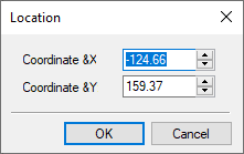
When editing a string text, its anchor point's coordinates can be changed using the parameters dialog.
Using a 2D node as an anchor point
Following objects can be selected as an anchor point
•an existing 2D node;
•joint of graphic lines belonging to a 2D projection;
•intersection of construction lines (a 2D node will be created automatically at the selected point);
•joint or intersection of graphic lines belonging to a 2D fragment (a 2D node will be created automatically at the selected point).
Upon selecting a type of text to be created, click ![]() the necessary object. The selected object becomes an anchor point of a text, so, upon further changes in object's position, the position of text will change accordingly.
the necessary object. The selected object becomes an anchor point of a text, so, upon further changes in object's position, the position of text will change accordingly.
Alternatively, you can use the following automenu option:
|
<N> |
Set relation with Node |
Upon activating the option, click ![]() anywhere on the drawing or active WP. The system will automatically detect the nearest existing 2D node or joint/intersection of graphic lines belonging to a 2D fragment and use it as an anchor point.
anywhere on the drawing or active WP. The system will automatically detect the nearest existing 2D node or joint/intersection of graphic lines belonging to a 2D fragment and use it as an anchor point.
Regardless of the way of selecting a node, following actions happen upon selection:
•In case of creating a multiline text or table, the system automatically creates a text at the at the selected node and switches to text content editing mode.
•In case of creating a paragraph text, the system switches to defining the next anchor point.
•In case of creating a string text, the system switches to defining horizontal and vertical offsets between the anchor point and the selected node. The preview of bounding rectangle continues following the cursor. An auxiliary line connects the selected node to the cross-shaped preview of the anchor point. Click ![]() at the necessary location to define offsets. As offsets are defined, the system switches to text content inputting.
at the necessary location to define offsets. As offsets are defined, the system switches to text content inputting.
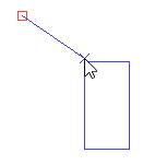
Offsets can be later edited using the text parameters dialog.
Orienting text along a construction line
String text can be oriented along a construction line (straight or circle) using following automenu options:
|
<L> |
Set relation with Line |
|
<C> |
Place Text around Circle |
Graphic lines as well as construction lines other than straight and circles could not be used for orienting a text.
Upon activating one of the aforementioned options, move the cursor over a line of suitable type. The line gets highlighted in green. Click ![]() to select the line. Next you need to define an anchor point in one of the ways described above. The selected line only affects text orientation without affecting its position.
to select the line. Next you need to define an anchor point in one of the ways described above. The selected line only affects text orientation without affecting its position.
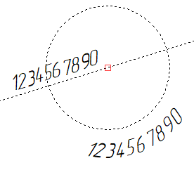
Text characters are placed normal to the selected line. The system automatically applies one of the two possible solutions. If the applied solution is not acceptable (the text is upside down), then you need to call the text parameters dialog and perform one of the following actions in the Style tab:
•Change the Rotation angle, in case of orienting the text along a straight line;
•Change the Vertical Justification to an opposite in case of orienting the text along a circle.
Position of text in relation to its anchor point
Before defining an anchor point for any type of text, you can call text parameters dialog using the following automenu option:

Among other parameters in the Style tab of the dialog there's the Justification group of parameters. This group contains drop-down list, where you can select Horizontal and Vertical positioning of the text in relation to its anchor point. The figures below show the examples of positioning the string text. For multiline text or table the combination of parameters selected in this dialog enables the corresponding automenu option. For paragraph text this parameters have no effect.
•Horizontal
|
|
|
|
|
Left |
Center |
Right |
Left&Center |
Right&Center |
The figure represents combinations of various horizontal justification options |
||||
•Vertical
|
|
|
|
|
Lower Limit |
Lower Base |
Center |
Upper Base |
Upper Limit |
The figure represents combinations of various vertical justification options |
||||
After creating the text, these options remain accessible in the parameters dialog for the string text only.
When editing the content of multiline text or table, an automenu option indicates the applied method of positioning the text in relation to its anchor point. You can switch to another option in one of the following ways:
•Click and hold ![]() a currently displayed option, until the drop-down menu appears. Then select the necessary option in the drop-down menu.
a currently displayed option, until the drop-down menu appears. Then select the necessary option in the drop-down menu.
•Click ![]() a currently displayed option once in order to switch to the next available option.
a currently displayed option once in order to switch to the next available option.
Following options are available:
|
|
Left Top |
|
|
Center Top |
|
|
Right Top |
|
|
Left Center |
|
|
Center |
|
|
Right Center |
|
|
Left Bottom |
|
|
Center Bottom |
|
|
Right Bottom |
Rotating a text using its parameters dialog
Before defining an anchor point for any type of text, you can call text parameters dialog using the following automenu option:
Among other parameters in the Style tab of the dialog there's the Rotation angle. It's an angle at which text is rotated about a horizontal axis. Measured in degrees. Positive values correspond to counterclockwise rotation, negative - clockwise. In cases where text is oriented along a construction line, such line will be used as rotation axis instead of horizontal.
After creating the text, this option remain accessible in the parameters dialog for the string text only.
Moving and rotating a text using manipulators
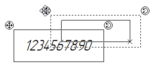
When editing the content of any text excluding the string text, if the text is not attached to a node, following manipulators are displayed at upper angles of a bounding rectangle:

![]() - move;
- move;
![]() - rotate around an anchor point.
- rotate around an anchor point.
Move the cursor over the necessary manipulator. As the cursor changes appearance to ![]() or
or ![]() , click and hold
, click and hold![]() , while moving the cursor. The text will move or rotate following the cursor. Establish the necessary position of the text and release
, while moving the cursor. The text will move or rotate following the cursor. Establish the necessary position of the text and release ![]() .
.
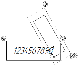
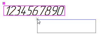
In order to move a string text, first move the cursor over it. As the pink frame and the square anchor point marker appear, you can start moving the text in one of the following ways:
1.Click ![]() within the frame or at the anchor marker. The blue contour of text's bounding rectangle will start following the cursor. Establish the necessary position of the text and click
within the frame or at the anchor marker. The blue contour of text's bounding rectangle will start following the cursor. Establish the necessary position of the text and click ![]() again. The text will move to the selected position.
again. The text will move to the selected position.
2.Click and hold ![]() within the frame or at the anchor marker and start moving the mouse without releasing
within the frame or at the anchor marker and start moving the mouse without releasing ![]() . The text will start following the cursor. Establish the necessary position of the text and release
. The text will start following the cursor. Establish the necessary position of the text and release ![]() . Moving the text in such way launches the Move with Translation mode of the 2D elements transformation command. Therefore, you can use any options available in said mode or switch to another transformation mode. In order to customize the transformation command' parameters, move the cursor outside the active view window and release
. Moving the text in such way launches the Move with Translation mode of the 2D elements transformation command. Therefore, you can use any options available in said mode or switch to another transformation mode. In order to customize the transformation command' parameters, move the cursor outside the active view window and release ![]() . From now on you won't need to hold
. From now on you won't need to hold ![]() anymore - the text will follow the cursor until you click
anymore - the text will follow the cursor until you click ![]() in a view window again.
in a view window again.

Additionally you can edit anchor point's coordinates in the string text parameters dialog.