Example of 2D Assembly > Visibility of Layers |
  
|
How to make it so that the complete drawing of a part could be used in an assembly drawing as a fragment? After all, in an assembly we do not need most of the part drawing with all its projections, dimensions and other design elements. In the our example we use layers for this purpose.
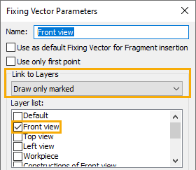
In fragment drawings graphic elements of different projections belong to different layers. Names of layers coincide with names of projections for convenience. All drawing annotations (dimensions, roughness symbols, title blocks) belong to other layers. For each projection a fixing vector is created and linked with the corresponding layer. In result, when we insert a fragment by fixing vector, only elements belonging to the linked layer are being displayed in the assembly.

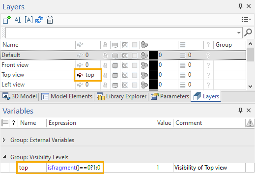
Sometimes a part drawing may need only one or two projections, but in an assembly we need to display the part on projections not included into part drawing. In the our example the Fork drawing contains only two projections - front view and left view, but the assembly drawing additionally contains the top view. So the top view in the Fork drawing belongs to the layer, whose visibility is managed by the top variable. The expression of this variable uses the isfragment() function, which outputs different values, depending on whether the fragment is displayed within assembly or separately. This layer is linked with the fragment's fixing vector as described above. In result, when the fragment is inserted into the assembly by this vector, only the top view layer is displayed, but in the fragment's document itself this layer is hidden.

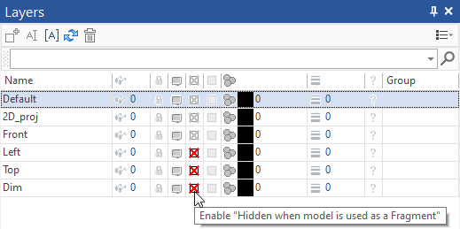
If an assembly drawing should contain only a single projection, but a part drawing contains multiple ones, you can just Enable "Hidden when model is used as a Fragment" option for layers that are not supposed to be displayed in assembly.
