Example of 2D Assembly > Variable Visibility Levels |
  
|
Variables can be used as visibility levels of drawing elements. Thus you can "add" or "remove" some elements depending on specified conditions.
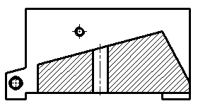
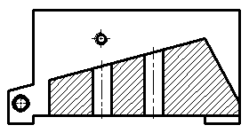
In the our example the drill jig design may change depending on the ratio between the workpiece length (the L variable) and the holes spacing (the l variable). If L value is at least three times higher than l value, two holes should be drilled in the workpiece, otherwise - one. Let's explore the techniques applied for changing the number of holes in the Body drawing automatically.


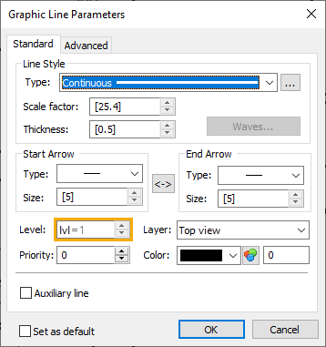
Visibility level of lines representing the second hole is managed by the lvl variable.

The value of this variable changes depending on the condition specified in its expression:
lvl = L>3*l?1:-1
External variables L and l are are linked with eponymous variables of the assembly and inherit their values automatically, when the fragment is inserted into the assembly. If L value is at least three times higher than l value, the visibility level of lines representing second hole is set to one, otherwise to minus one. In the Body document visibility intervals for all types of elements are default - from 0 to 127. Same intervals are applied, when displaying the Body in the assembly, because it is inserted with Parameters from Fragment. Therefore, when the level is -1 lines representing the second hole are displayed, and when the level is 1 - not displayed.
The hatch is managed in the same way. Two hatches are created - one with the single hole and another with two holes. The visibility level of the hatch with two holes is managed by the same lvl variable. The visibility level of the hatch with the single hole is managed by the -lvl expression, i.e. it is the value of the lvl variable with an opposite sign. In result, only the hatch corresponding to the current number of holes is displayed in the assembly.
Variables may also be used for defining visibility levels of elements in an assembly drawing. Depending on the number of holes to be drilled, the drill jig may consist of different fragments - the second hole requires two additional drill bushings fixed with the additional screw. If you define visibility levels of these fragments by the same lvl variable, they will be displayed in the assembly only when there are two holes.
However, in our example we achieved it in a different way - using variable fragments. Both approaches affect not only the display of elements in drawing, but also their inclusion into product composition, because the Don't include invisible objects checkbox is enabled in product composition parameters by default. Variable fragments allow not only to manage visibility fragments, but also to use different fragments in the same fragment insertion operation, depending on a condition specified in variable's expression.