Example of 2D Assembly > Managing Fragments' Variables in Assembly |
  
|
Geometry of fragments in assembly should be harmonized with each other. In order to ensure the correct automatic recalculation of geometry of all parts, upon changing a value of some part's parameter or an assembly variable, you should link variables of fragments with each other or with variables of assembly. T-FLEX CAD provides multiple tools for establishing such links :
•automatic link with assembly variable;
Automatic link with assembly variable
If you need to link an external variable of a fragment with any variable of an assembly, you can specify a name of the corresponding assembly variable in the parameters of the fragment variable. Upon inserting the fragment, its variable automatically inherits the value from the specified assembly variable. If there's no such variable in the current assembly, the fragment variable keeps the value specified in the fragment document.
In the our drill jig example, this method is used for passing values of following parameters from assembly to body lid and fork fragments:
•specified arbitrarily by the user - dimensions of the workpiece (height H, width W, holes diameter D, angle A, chamfer size C, holes spacing l, length L), gap (gap), height of legs (Hlegs);
•selected from the list by the user - pins diameter (Dpins), lid fixing screws diameter (dhex);
•calculated automatically - pins lengths (Lpin) and (lpin), handle mounting diameter (d4handle), counterbore diameter (Dbore), position of locking screws (Ascrew), lid thickness (Hlid).
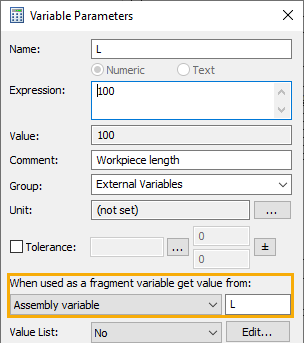
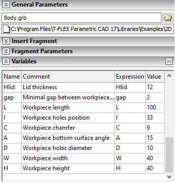
If you don't know the name of the corresponding assembly variable at the moment of creating the fragment, or if you need to link the same fragment variable with different assembly variables in different assemblies, you can link fragment variables with assembly ones, using the fragment's external variables dialog upon its insertion, but this would require setting the link manually for each instance of the fragment.
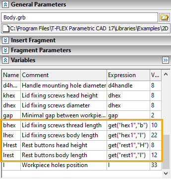
The get() function can be applied for passing values of variables between fragments in assembly. The function should be used in the expression of the target variable in the fragment's external variables dialog. The first argument of the function is the name (if the source fragment is manually named) or ID of the source fragment, the second argument is the name of the source variable. Both arguments should be put into quotes.
In the our drill jig example, this function is used for passing dimensions of rest buttons into body, lid and fork fragments, as well as for some other purposes. Short names are manually assigned to source fragments for clarity of expressions; the same names are used as suffixes in names of variables, which represent the parameters of such fragments in the assembly and in other fragments: rest, drill (drill bushing), liner (liner bushing), body, lid, eye (eye bolt), hex (lid fixing screw).
Connectors aren't just fragments fixing elements. Additionally they can be used for passing values of variables between fragments. To do so, create a connector and specify its values in source fragment, then specify corresponding connector values in parameters of variables in target fragment. Variables of the target fragment should be external. Then insert the target fragment by a fixing vector and use the connector of the source fragment for its positioning. In result the variables of the target fragment will inherit the corresponding connector values. If there are no corresponding values, the variables of the target fragment will keep values specified in its file.
This approach is most useful, when inserting standard parts into holes on plan views.
In the our drill jig example, this approach is used for passing diameters and lengths/heights of screws and bushings inserted into holes of the lid on the top view, as well as for passing diameters and lengths of pins inserted into holes of the body and lid on the front view.
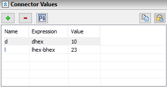
Connector values of the Body

Variables of the screw
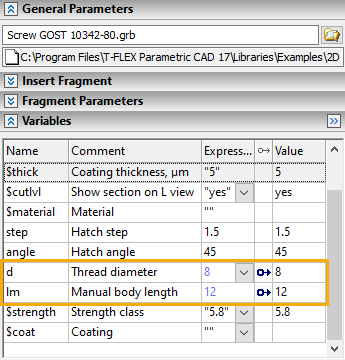
Variables of the screw linked with connector in assembly