Parameters of Variable |
  
|
To change the name, expression, or other characteristics of already created variables, use the variable parameters dialog. The dialog may be invoked, using the following command:
|
<Ctrl>+<M> |
Variable > Parameters... |
The ![]() Parameters command can also be called from the context menu called by
Parameters command can also be called from the context menu called by ![]() when you select a variable in the variable list. Or, you can call it by simply pointing the cursor at the variable name in the variable list and clicking
when you select a variable in the variable list. Or, you can call it by simply pointing the cursor at the variable name in the variable list and clicking ![]()
![]() .
.
The parameters dialog is also invoked automatically, when creating a new variable.
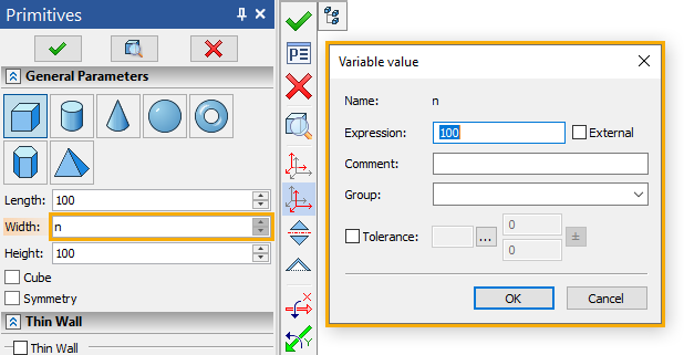
If a variable is being created via typing an unused name into an input box of some parameter of a drawing/3D model element, the short version of the dialog is displayed, because some of the parameters (such as type or units) are predefined by the nature of the corresponding parameter of the element.
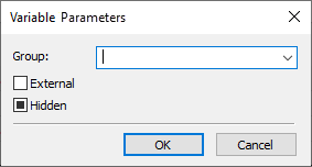
The ![]() Parameters command can also be called for multiple selected variables. In this case, the dialog contains only a few parameters, which can be changed for all selected variables at once. A filled checkbox
Parameters command can also be called for multiple selected variables. In this case, the dialog contains only a few parameters, which can be changed for all selected variables at once. A filled checkbox ![]() means that is is enabled only for some of the selected variables.
means that is is enabled only for some of the selected variables.
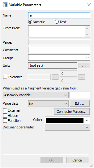
The full version of the dialog contains following parameters:
•Name;
•Type (Numeric/Text);
•Value;
•Comment;
•Group:
•Unit;
•When used as a fragment variable get value from;
•External;
•Hidden;
•Function;
•Color;
•Link with T-FLEX DOCs and other integration parameters.
A name of a variable should be unique within the current document, i.e. you can assign a name already used by another variable. Name may only contain letters, numbers and underscores. First character of a name should be a letter. The $ character is added in front of a name for text variables.
Names are case-sensitive, e.g. A and a are different variables.
Local language extensions of US ASCII are supported for the names. Local language users shall keep in mind that some language characters (particularly, Cyrillic and Greek) resemble the standard US ASCII, while their system codes may be different. Therefore, care should be taken, as names with the same appearance yet actually composed of different characters are considered different names, e.g. Latin A and Cyrillic А are different names. It is recommended not to use such local languages for names of variables, because, when using functions and variables in the same expression, you would need to switch input language, as function names are composed of Latin characters.
It is also recommended to use short names for variables, as long names would cause very long expressions. A detailed description of a variable can be provided as a comment.
Examples of correct variable names:
•VAR1
•V
•VAR_1
•$TEXT
•WIDTH
•width
Examples of inappropriate variable names:
•1_VAR (the first character is not a letter);
•!_VAR! (inadmissible “!” character is used);
•V A R (the name may not contain “space” characters).
A name of a variable may coincide with a name of a function.
Names from x1 to x99 and from y1 to y99 are reserved for coordinates of fixing points of 2D fragments. Using these names for other purposes may cause errors.
Type of variable defines the data type of variable value: Numeric - real number, Text - textual string (sequence of characters). Numeric variables are created by default. It is easy to understand type of a variable by its name - if first character of a name is $, then the variable is textual..
The Name input box and the Numeric/Text switch work in a synchronized manner. For example, if the specified name of the variable starts with $, then the type is automatically switched to Text; if the $ character is removed, the type is automatically switched back to Numeric. And vice versa – upon changing the type of the variable, the $ character is automatically added/removed to/from the name of the variable
An expression – is a mathematical formula, to be used for calculating value of variable.
An expression can contain operands (constants and variables), operations (actions on operands) and functions (standard and custom). Operands used in an expression of a variable should belong to the same type as such variable (numeric or text). Different operations and functions can be used depending on the type of variable.
When inputting expressions, keep in mind that names of variables are case-sensitive, while names of functions aren't.
An expression can represent itself just a constant (numeric or text depending on the type of variable).
Same as other input boxes, the expression input box in the variable parameters dialog allows usage of contextual menu commands, such as Enter Angle or commands related to list of values. Notice, that the list of values in the variable expression input box is not the list of variable values itself.
Value of variable is calculated by the system using the expression specified above. It is indicated in the non-editable Value box below the expression. In order to change the value, edit the expression.
If necessary, for any variable the comment can be specified. It represents itself an arbitrary text string. The comment allows to “attach” certain explanations to the variable. For example, the comment may clarify the variable's purpose (the width of the part, the radius of the circle, etc.) or the range in which the value of the variable is changed.
The comment of the variable, if it is specified, is displayed in the expression constructor, in the variable editor, in the Variables tool window and in the list of fragment's external variables.
Groups are used for grouping variables in the editor and Variables window. When variables are grouped, it is easier to manage large list of variables of complicated drawing.
The fact that the variable belongs to a certain group does not affect in any way the usage of this variable. See more in the Grouping Variables section.
By default, the parameter Group takes the same value, as the one of the variable selected in the list of variables at the moment of calling the variable creation command.
Real variables can be dimensionless, when its unit of measurement is not specified, or have a specific unit of measurement. If unit is not specified by the user, it may sometimes be defined automatically based on an expression. When calculating the values of expressions, the compatibility of the units of measurement is checked. In case of non-compatibility, the system displays a warning message. The units of the variable is optional and in many cases unnecessary. See more in the Units of Variable Value Measurement section.
Enabling the Tolerance checkbox allows you to set a tolerance zone (range) and deviations for the variable, in the same way, as it's done for dimensions, using controls located to the right.
When used as a fragment variable get value from
If the current document is going to be used as a fragment, you can specify an assembly parameter, whose value will be inherited by the external variable of the fragment upon insertion into assembly. The parameter is specified using the When used as a fragment variable get value from drop-down list. If the parameter is set to Assembly variable, you should type the name of the corresponding assembly variable into the input box located to the right of the drop-down list.
in the Assembly variable parameter field in the .

The group of parameters Value List allows to create and edit the list of values for a variable. If a given variable does not have the list, then the No value will be specified in the drop-down menu of the given group. For creating the list it is necessary to select from the menu the required creation method: Text, Database, File, Data, Materials. More detailed description of various methods of creating the list of variable’s values is presented in the Creating List of Values for Variable section.
Any variable, the value of which is specified by a constant (numeric or text), can be assigned the External attribute via enabling the eponymous checkbox. External variables are used for organizing associative link between the assembly document and the fragments. The values of the external variables, defined in the fragment, can be changed from the assembly document. See more in the External Variables section.
The variables, marked as external, can be exported to an external text file with the possibility of reading from this file afterwards. This allows to use external variables for organizing connection between the T-FLEX CAD and other systems and application programs.
In the list of variables names of external variables are shown in bold.
Hidden
Any variable in a T-FLEX CAD document can be Hidden via enabling the eponymous checkbox. Hidden variables are not displayed by default in the window of the variables editor and other T-FLEX CAD windows dealing with the variables. Thus, it is possible to hide various auxiliary variables. See more in the Hidden Variables section.
Besides various standard functions, predefined in the system, it is possible to define custom functions and use them in expressions of variables. For example, if many similar, bulky expressions, differing only in some arguments, are used for defining variables, it is possible to define custom function, which can replace such expressions. Custom functions are defined with the help of variables of a special kind – variables-functions.
Variable-function represents the definition of custom function. The expression for variable-function is composed according to the same rules as those for standard variables. Arguments of the function are represented in the expression in the following way (the number of the arguments is not limited):
#1 – the first argument,
#2 – and second argument and so on.
For a variable to be recognized as a custom function, you should enable the Function checkbox in its parameters dialog. The function defined in such way can be used in the variables editor for specifying values of other variables. When calling this function, use names of variables or numeric expressions as the arguments. The number of actual arguments must be equal or more than the number of formal arguments.
For example, if the variable-function was defined in the following way:
FUNC=(#1+#2)*10
the call FUNC (L, 20, 30) will not be a mistake: the function will just use first two argument only - L and 20.
In the list of variables of the current document, empty brackets “()” are automatically added to names of variables-functions.
The list of connector values is set in the Connector Values dialog box that appears when the corresponding button is clicked.
The list Connector Values… is filled for external variable of a document, used as a fragment with fixing by connector. Upon inserting such fragment into an assembly, the system has to automatically change the value of the fragment's external variable in accordance with the value of the connector specified in this list. Upon fixing the fragment to the connector, the system will be first looking for the first name from the list, among the named connector values, and if it is not found – the second name and so on. More information on connectors can be found in 2D Connector and 3D Connector sections.
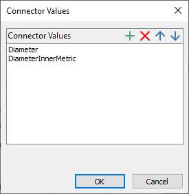
The list of connector values may contain arbitrary number of elements.
For creating a new element of this list, the button ![]() is used in this window, for removing already existing element – the button
is used in this window, for removing already existing element – the button ![]() . The buttons
. The buttons ![]() and
and ![]() enable to move elements up and down along the list (the order of the elements in the list is set by a priority of elements in the list upon searching for the coincidences with the connector values).
enable to move elements up and down along the list (the order of the elements in the list is set by a priority of elements in the list upon searching for the coincidences with the connector values).
The Color parameter specifies the color of the variable name in the variable editor.


By default, variables have black color. If the Syntax Highlighting is enabled, the black color specified in parameters of variable is ignored and the system uses other colors instead.
The Document parameter allows you to establish a link between the value of a variable and file properties. The drop-down list allows you to select the name of the property that will be equal the value of the variable. These properties cannot be seen in the Windows Explorer, but can be accessed by external applications (e.g: T-FLEX DOCs) without reading the whole file.
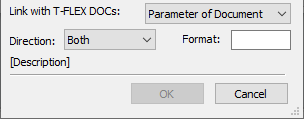
Within the T-FLEX DOCs integration mode, the bottom section of the variable parameters dialog contains parameters responsible for link between variables of T-FLEX CAD and variables of T-FLEX DOCs (see the section).
See Also: