Dimensional Tolerance |
  
|
In the Tolerance tab of the ![]() Dimension command's parameters window you can define tolerance, fit and limit deviations.
Dimension command's parameters window you can define tolerance, fit and limit deviations.
The parameters of this tab are non-applicable to level markers.
Non-angular dimensions
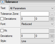
Following parameters can be defined in the Tolerance tab for non-angular dimensions:

Text
The drop-down list of this parameter defines, which parameters will be displayed together with the dimension nominal value:
•Nominal. Only the dimension value is displayed

•Nominal + Deviations. The limit deviations are displayed next to the dimension value.

•Nominal + Tolerance. The tolerance range will be displayed next to the dimension value.

•All parameters. In this case, both the tolerance range and the limit deviations are displayed.

•Limits (ANSI standard). The dimension value is composed of the two main values, each being the sum of the dimension value and the corresponding limit deviation.

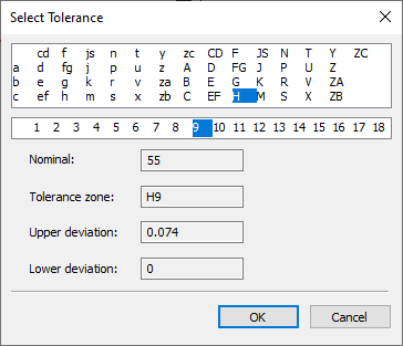
Tolerance zone (range) can be inputted manually or selected from the dialog. The dialog can be invoked via the [...] button located to the right of the tolerance zone input box.
Tolerance zone designation consists of a letter representing fundamental deviation, and a number representing tolerance grade.
In order to define the fundamental deviation, click its letter in the table located in the upper section of the dialog; in order to define a tolerance grade, click its number below the table.
The bottom section of the dialog indicates dimension's nominal value, resulting designation of the tolerance zone and limit deviations calculated automatically considering the tolerance zone and the dimension value. Whether these deviation values will be used in dimension's parameters or not, depends on the status of the Deviations checkbox described below.

The document parameters include the non-displayable tolerance grade (Document Parameters > Page > Dimensions > Dimensions > Non-displayable tolerance grade). If a tolerance grade of a dimension coincides with the non-displayable tolerance grade, then the value of such dimension will always be displayed in drawing without tolerance parameters, regardless of the option selected in the aforementioned Text drop-down list.
This checkbox is disabled by default, so the limit deviations are calculated automatically, considering the tolerance zone and the dimension value. If you enable the checkbox, the deviation values should be typed manually into two input boxes located aside with the checkbox. The calculation results depend on the units of measurement set in document parameters (Document Parameters > Page > Paper > Paper > Units). Automatic deviations calculation works only for millimeters and inches. When the dimension value is modified, the automatically calculated deviations will be recalculated.
A variable can be entered as a deviation value just like in any other numerical input box
[±] button located to the right of the deviation input boxes allows to quickly set the value of the lower deviation same as the one set for the upper deviation.
Font
Different standards set the different requirements to the font size of deviation values in the drawing. Two options are provided: Reduced, which is half the font size, and Full.
Fit
This checkbox is disabled by default, so only a single tolerance zone is displayed. Upon enabling the checkbox, the fit will be displayed, which is represented as a fraction. The hole's tolerance zone is displayed in the numerator, the shaft's tolerance zone is displayed in the denominator. The tolerance zone set in the upper section of the Tolerance tab is considered a hole's tolerance zone. The shaft's tolerance zone is set in the lower section of the Tolerance tab using the input box and the [...] button located to the right of the Fit checkbox. The shaft's tolerance zone is defined in the same way as the hole's tolerance zone.
Deviations
Limit deviations of the shaft are defined in the same way as the limit deviations of the hole.
Style
One of the following fit display formats can be selected in this drop-down list:
•Line
![]()
•Fraction

Angular dimensions

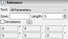
Since angular dimension tolerance calculation depends on the length, the Length parameter is provided for angular dimensions. For the calculating deviations automatically, enter the tolerance zone in the following format: +AT8, AT8 or -AТ8, where 8 is the tolerance grade, while a signed AT defines the tolerance type.


The angular deviations are calculated in degrees, minutes and seconds. Each of these units has its own input box.
Fits are non-applicable to angular dimensions.