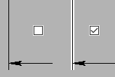
Style of Dimension |
  
|
Style of dimension includes configuration of dimension and witness lines, presence of special dimension symbols and orientation of dimension value. The style is defined using the Style tab of the ![]() Dimension command's parameters window. The main dimension symbol may also be changed using the automenu. The Style tab contains following parameters:
Dimension command's parameters window. The main dimension symbol may also be changed using the automenu. The Style tab contains following parameters:
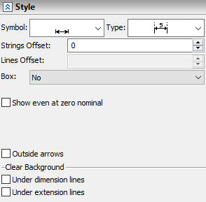
A special symbol to be displayed before the dimension value. In the drop-down list you can select ![]() absence of a symbol, or symbols of
absence of a symbol, or symbols of ![]() radius,
radius, ![]() diameter,
diameter, ![]() metric thread,
metric thread, ![]() square,
square, ![]() sphere,
sphere, ![]() taper and
taper and ![]() conicity. This parameter is not available for some categories of dimensions.
conicity. This parameter is not available for some categories of dimensions.
Dimension symbol may also be changed using the following automenu option:
|
<D> |
Change dimension symbol |
|
|
No |
|
|
Radius |
|
|
Diameter |
|
|
Thread |
|
|
Square |
|
|
Sphere |
|
|
Taper |
|
|
Conicity |
For linear dimensions, activating this option by pressing the <D> hotkey or by simple clicks ![]() on its automenu icon results in sequential switching between all available symbols, without affecting the dimension value. The icon displayed for this option on the upper level of the automenu
on its automenu icon results in sequential switching between all available symbols, without affecting the dimension value. The icon displayed for this option on the upper level of the automenu ![]() represents the currently selected symbol. If you press and hold
represents the currently selected symbol. If you press and hold ![]() on this icon, the drop-down list will appear allowing you to directly select any of the available symbols.
on this icon, the drop-down list will appear allowing you to directly select any of the available symbols.
For radial dimensions, activating this option by pressing the <D> hotkey or by simple clicks ![]() on its automenu icon results in sequential switching between
on its automenu icon results in sequential switching between ![]() radius,
radius, ![]() generic diameter and
generic diameter and ![]() nominal diameter of metric thread, where dimension value also changes depending on whether the radius or the diameter is displayed. In such selecting the
nominal diameter of metric thread, where dimension value also changes depending on whether the radius or the diameter is displayed. In such selecting the ![]() square and
square and ![]() sphere symbols in the automenu may only be performed via invoking the drop-down list, while other symbols are only available in the parameters window.
sphere symbols in the automenu may only be performed via invoking the drop-down list, while other symbols are only available in the parameters window.
For some types of dimensions the symbol change option has different appearance and way operation:
|
<D> |
Change Sign |
This version of the option doesn't contain the drop-down list, so you can only switch sequentially between all available symbols.
Moreover, you can select a symbol directly in drawing or 3D window using the special toolbar ![]() , which can be invoked by clicking
, which can be invoked by clicking ![]() either a
either a ![]() dimension symbol manipulator (if symbol is not set), or an existing symbol.
dimension symbol manipulator (if symbol is not set), or an existing symbol.
Type
In the drop-down list you can select a desired configuration of witness and dimension lines. This parameter is required, if you need to have a linear dimension without witness lines (this is often used when creating dimensions from an axis). This parameter can also be used to create one-sided dimensions (used for dimensioning on cut views or for dimensions on large-size parts). This parameter is not available for some categories of dimensions.
Configuration of dimension and witness lines may also be changed using the <M> Change Dimension Type automenu option. Configurations provided by this option differ from configurations available in the parameters window, so the resulting appearance of dimension is achieved by combining usage of the automenu and the parameters window. The set of configurations available in the automenu depends on the dimension creation method. Configurations available in the automenu are described separately for each dimension creation method in help sections describing particular methods.

Strings offset
The distance by which the dimension value and accompanying text strings will be separated from a dimension line or from a shoulder in addition to the default offset.
Lines offset
The offset of witness lines from source object, when creating dimensions per the ANSI and BS308 standards. For DIN/ISO standard this parameter is not applicable. Whenever this parameter is not defined, the offset will depend on the size of the dimension line arrows.
The figures below demonstrate the effect of setting value of this parameter equal to "0" and "5".


This parameters defines frame, which encloses dimension value and text strings before and after the value. You can choose one of the following options from the drop-down list:
|
|
|
No |
Square |
Rounded |
If you need a frame enclosing only some part of the string displayed over or under the dimension line, use the %%R or %%r special code in the input box of the corresponding text string. In result the frame encloses only the part of the string between two mentioned symbols. The Box parameter doesn't affect the frame defined via special symbols.

A frame may also be added by putting a ~ (square frame) or ` (rounded frame) symbol at the start of the Before string (both Before and After string will be framed along with the value) or at the start of the Under string (only the Under string will be framed). Same symbols at any other position are treated as part of the string and do not affect the frame.
Other special codes and symbols may also be used in a dimension. E.g.: %%u and %%o codes add underscore and overscore correspondingly.
Below there are checkboxes of various options. Number and nomenclature of available checkboxes depend on the dimension creation method. Following checkboxes might be available:
•Outside Arrows
When this flag is set, the dimension arrows are always drawn outside of the extension (witness) lines. When the flag is disabled (the default), the arrows position is determined automatically depending on the distance between the extension lines of the dimension. If arrows don't fit inside, then those will be automatically switched to outside.
•Show even at zero nominal
When this parameter is enabled, dimension will be displayed on the drawing even when its value is zero.

•Leader Line (for level markers)
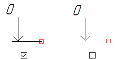
•Show "Plus" (for level markers)
•Text along the line (for angular dimensions)
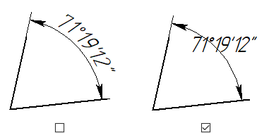
•Arc symbol (for arc dimensions)


The Clear Background group of checkboxes allows to disable the display of drawing image around the dimension and witness lines. The background is cleared by both sides of the corresponding line at a distance equal to the default thickness of the continuous line.
•Under dimension lines
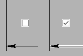
Background under the arrows can be cleared using the Arrows tab individually for each arrow.
•Under extension lines (under witness lines)
