Selecting Edges for Blending |
  
|
After calling the Edge Blend command, the element input field is active, allowing you to select all elements suitable for creating the operation.
Upon calling the command the Edges tab on the General Parameters section of the Parameters window becomes active, as well as the corresponding automenu option:
|
<E> |
Select Faces, Edges, Vertices |

This automenu option and the Edges tab are linked together: activation of the tab activates the automenu option and vice versa. This mode enables filters for selecting 3D elements allowed for defining edges on the Filter Toolbar. Then you can select object in the 3D scene by moving mouse cursor over it and clicking ![]() . When selecting elements, pay attention to active filters.
. When selecting elements, pay attention to active filters.
![]()
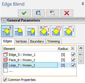
Edges tab contain the list of elements.
Upon selecting an operation all edges of the corresponding body are added to the list. The body itself isn't added to the list.
Upon selecting a vertex all edges meeting at this vertex are added to the list. The vertex itself isn't added to the list.
Using vertex for selecting edges is the only way to automatically enable offsets.
Upon selecting a face it is added to the list and blend parameters are applied to all edges of such face. Remember that selected face will always be considered the first blend surface.
Upon selecting a loop it is added to the list and blend parameters are applied to all edges in a loop. Remember that face framed by a selected loop will always be considered the first blend surface.
The way of selecting edges for blending (directly or using loops and faces) affects operation regeneration upon further changes of initial geometry.
Edges and loops added to the list are highlighted in green in the 3D scene, faces are highlighted in blue, current selection is highlighted in red.
Buttons allowing to ![]() Collapse the list,
Collapse the list, ![]() Delete Element from the List or
Delete Element from the List or ![]() Clear the list are located to the right side of the list. Click
Clear the list are located to the right side of the list. Click ![]() on element in the list to select it. Selected element will be highlighted in the list.
on element in the list to select it. Selected element will be highlighted in the list.
List is represented in a tabular format.
The first column Element contains an element type icon (edge, face or loop), a name of an element and a name of a parent body.
The second column Radius contains one or two numerical values. Depending on the selected blend type such values may represent radii, offset 1 and offset 2 or length. Values could not be edited directly from the list. Use corresponding fields below the list instead. If Common Properties checkbox is enabled for selected element, value in Radius column are displayed in square brackets. Disabling the checkbox removes brackets.
The third column Leave Selected contains the checkbox which applies blend to this particular element. It's enabled by default. Disabling such checkbox will exclude corresponding element from the blend. However excluded element will remain in the list after operation creation.
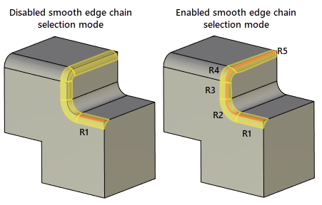
The smooth edge chain selection mode can be activated using the following automenu option:
|
<S> |
Smooth edge chain selection mode |
A smooth chain is a set of edges making an open or closed continuous smooth curve (with a tangent continuity (G1)).
When using this mode, all edges that can make a smooth chain together with the selected edge are added to the list automatically.

Propagating blend on tangent edges.

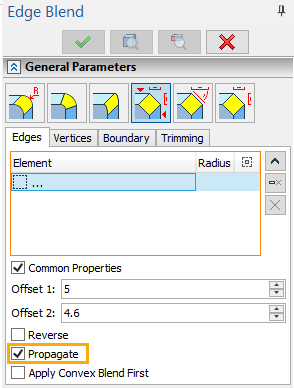
The Propagate checkbox is available for all types of blend. This functionality searches for a smooth continuation of the currently blended edge. A smooth chain may exist originally or form as new edges are created on the blend boundary. In the case of successfully defining a smooth chain the system attempts to propagate the blend along the whole chain.
The automenu option ![]() described above has a similar purpose. However, when selecting an edge with automenu option, all elements of the identified chain are included in the list. When using the Propagate checkbox, the list may not contain all edges of the blended chain, rather, could be just one edge.
described above has a similar purpose. However, when selecting an edge with automenu option, all elements of the identified chain are included in the list. When using the Propagate checkbox, the list may not contain all edges of the blended chain, rather, could be just one edge.
This is important in view of possible topology changes of the model when the smooth chain contents may change. It's enough to select just a single most stable edge of the whole chain to be blended.
If the Common Properties checkbox is disabled for selected edge, the Propagate checkbox is applied to such edge only. Otherwise Propagate checkbox is applied to all edges with Common Properties enabled.