Spine of Face Blend |
  
|
The spine defines positions of the ![]() Face Blend cross-section planes for disc and isoparametric blend types. If the spine is too short for constructing the whole blend surface, the system extends the spine by straight segments tangent to the selected spine curve at the ends. If the spine is longer than required, the system will attempt automatically define the necessary portion.
Face Blend cross-section planes for disc and isoparametric blend types. If the spine is too short for constructing the whole blend surface, the system extends the spine by straight segments tangent to the selected spine curve at the ends. If the spine is longer than required, the system will attempt automatically define the necessary portion.
Also the spine is necessary for specifying the ![]() law of radius or offset change, in cases of variable radius or variable offset blend.
law of radius or offset change, in cases of variable radius or variable offset blend.
The spine may be a 3D path, a 3D profile, edge, loop or face (in the latter case, edges limiting the selected face are used). The spine can be selected in the 3D window or in the model tree using the mouse. The name of the selected 3D path is displayed in the parameters window.
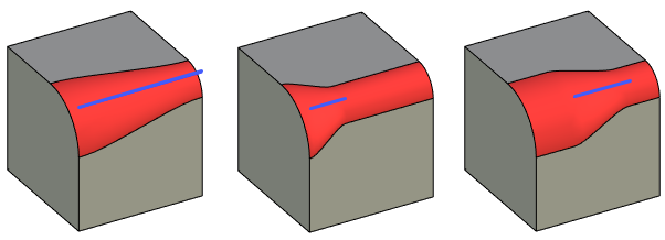
An example of creating blending, taking into account the different lengths of the spines
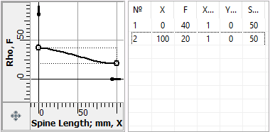
The graph below uses a cubic spline. At the start point, the blend radius is 40, and at the end point it is 20.

In the figure below you can see how the blend surface changes, depending on the length and location of the spine with the same graph.The spine is highlighted in blue.
