Modes of Face Blend |
  
|
Blend modes define the ways of computing the blend surface bounds in the current cross section. Only the bounding points (points of contact) are computed in the cross sections of the blend surface. What will be constructed in between the bounding points depends on the chosen shape of the blend surface.
Following modes are available in the ![]() Face Blend command:
Face Blend command:
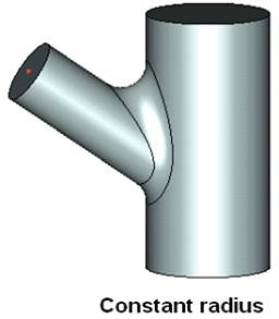
In this mode, the blend spine is equidistant from both left and right walls by the distance R in all blend surface cross-sections. The distance R can be set as variable with the help of a graph.
|
1. Left wall 2. Right wall 3. Blend spine |
The term "radius" in the mode name is just a convention. In fact, this mode allows to create not only the conic-shape roundings, but also chamfers and surfaces of continuous curvature depending on the specified blending shape. With the conic shape of the cross section selected, a surface is constructed with each cross section being a circular arc of a specified radius.
In this mode, the blend spine is positioned at non-equal distances d1 and d2 from the left and right wall accordingly. These distances can be set as variable with the help of a graph.
|
1. Left wall 2. Right wall 3. Blend spine |
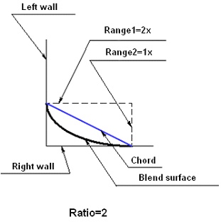
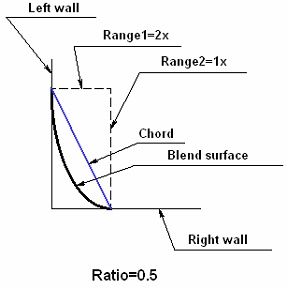
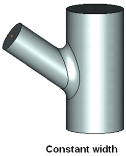
In this mode, the withd of the chord d between the left and right walls contact points is constant along the extent of the blend. For this mode you can specify a ratio between the contact point offset d1 on the right wall and the offset d2 on the left wall. The ratio value other than 1.0 creates an asymmetric blend with the constant chord width.
|
1. Left wall 2. Right wall 3. Blend surface |


This type of blending is especially desirable when the angle between the blended faces varies across the extent of the blend. In this case, one may want to specify approximate amount of cross section additional material to be maintained along the blend.


Width mode only works with Rolling Ball type blend.