Shape of Face Blend |
  
|
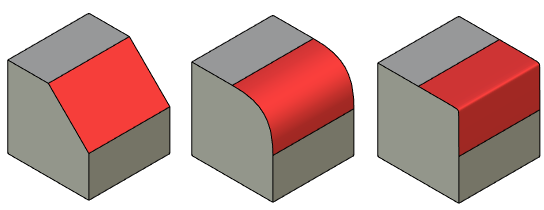
Following shapes of the blend surface cross-section are available in the ![]() Face Blend command:
Face Blend command:
|
|
1. Left wall 2. Right wall 3. Cross-sectional planes |
4. Contact lines 5. Contact points 6. Cross sections of blend surface |
The conical shape of the blending can be a circle, an ellipse, a parabola, or a hyperbola.
|
1. Left wall 2. Right wall 3. Blend surface 4. Contact points |
The Convexity (Rho) option affects the creation of a conical section shape.
![]()
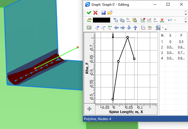
If the Convexity parameter is not used, a blend surface cross section will have a shape of a circle, if the blend is symmetric, and a shape of an ellipse, if the blend is asymmetric. To use this parameter, you can define the convexity value in the range 0 < k < 1. If convexity value is 0 < k < 0.5, the blend surface becomes an ellipse, in the case k=0.5 – a parabola, and in the case 0.5 < k < 1 – a hyperbola. The convexity can be set as variable with the help of a graph.
|
1. Left wall 2. Right wall 3. Blend surface |

Three bodies with different convexity values (0.001, 0.5, 0.999)
In the Offset mode, the shape of the conic section depends on the settings of the mode itself, in particular, on the Offset parameter. If the offset ratio is set to 1, then a circular arc will be formed in the section of the blend surface, otherwise the section will be a parabola.
If you set a graph, you will need to specify a spine.

When choosing the Chamfer shape, a regular chamfer is built with a given radius. Additional adjustment of this section shape is not required under any blending modes. The contact points calculated according to the selected mode in each cross section are connected by a straight line.
|
1. Left wall 2. Right wall 3. Blend surface 4. Contact points |
In the chamfer cross-section the contact points, computed for each cross section, are connected by a curve that has the same curvature as each wall at the contact points.
|
1. Left wall 2. Right wall 3. Blend surface 4. Contact points |
It is possible to implement a section that is continuous in curvature only with a spherical blending type, therefore, when this section shape is selected, the system automatically switches to the rolling ball blend type.
For the Continuous Curvature shape, it became possible to select Type. Two types are available - Softness and Depth.
The Softness parameter controls how quickly the curvature of the blend changes from that of the underlying faces as you move along the blend cross-section from contact points to the center of the blend.
The minimum value of the softness coefficient tends to zero, the maximum is not limited. At the minimum value of the coefficient, the shape of the cross section of the blending surface tends to the shape of a chamfer, at a large value - to the shape of a right angle.
|
1. Left wall 2. Right wall 3. Blend surface |

Three bodies with different softness values (0.001, 1, 10)
For the Depth type, it is possible to set the Offset and Depth values. These coefficients jointly determine the position of the point with the maximum blending depth in the current cross section - the blend vertex.
The Offset parameter indicates the position of the depth point along the chord between the contact points. It can take a value 0 < k < 1. Values close to 0 represent points close to the left wall, values close to 1 represent points close to the right wall. The offset can be set as variable with the help of a graph.
|
1. Left wall 2. Right wall 3. Depth point |

Three bodies with different offset values (0.2, 0.5, 0.8)
The Depth parameter indicates the position of the depth point along a line between the chord connecting the blend’s contact points and the intersection of the tangents of the walls. It can take a value 0 < k < 1. Values close to 0 represent points close to the chord, values close to 1 represent points close to the intersection of the tangents of the walls. The depth can be set as variable with the help of a graph.
|
1. Left wall 2. Right wall 3. Depth point |

Three bodies with different depth values (0.1, 0.5, 0.9)