Boundaries of Face Blend |
  
|
Boundaries of Face Blend |
|
By specifying the blending boundary, one can unambiguously determine the position of the contact line on specific sections of the blending surface. This is necessary to take into account the edges of the faces when constructing the blend surface, when the blend surface goes beyond the edges of the blended faces. In this case, this option allows you to bring the blend surface to the edges of the faces with automatic calculation of the size of the blend surface.
Blend result without boundary conditions |
Blend result with two-face inverted tangency |
|
|
Following boundary conditions are available in the ![]() Face Blend command:
Face Blend command:
This type of boundary condition setting is used, when the blend surface, which follows the blended faces edges as a boundary, locally tends to have a smaller blend size than that specified by a user. In other words, in this case the blend surface locally overlaps the edges of the faces.
If two-face tangency is set, then the opposing contact line of the blend surface is modified symmetrically.
Blend result without boundary conditions |
Blend result with two-face tangency |
|
|
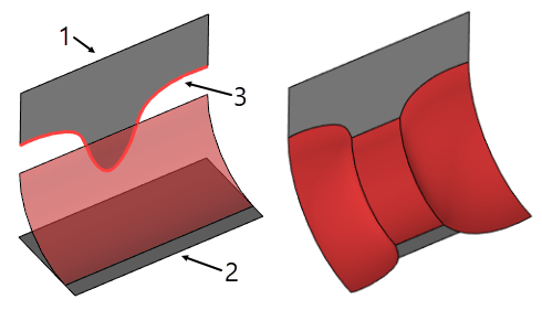
1. Left wall 2. Right wall 3. Specified blend boundary |
|
This type of boundary condition setting is used, when the blend surface, which follows the blended faces edges as a boundary, locally tends to have a smaller blend size than that specified by a user. In other words, in this case the blend surface locally overlaps the edges of the faces.
If one-face tangency is set, then the opposing contact line of the blend surface is not disturbed and follows the law, described by surface parameters.
Blend result without boundary conditions |
Blend result with one-face tangency |
|
|
1. Left wall 2. Right wall 3. Specified blend boundary |
|
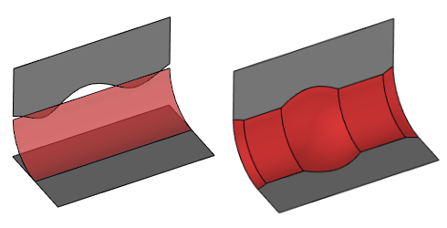
This type of boundary condition setting is used, when the blend surface, which follows the blended faces edges as a boundary, locally tends to have a bigger blend size than that specified by a user. In other words, in this case the blend surface locally doesn’t reach the edges of the faces.
If two-face inverted tangency is set, then the opposing contact line of the blend surface is modified symmetrically.
Blend result without boundary conditions |
Blend result with two-face inverted tangency |
|
|
1. Left wall 2. Right wall 3. Specified blend boundary |
|
This type of boundary condition setting is used, when the blend surface, which follows the blended faces edges as a boundary, locally tends to have a bigger blend size than that specified by a user. In other words, in this case the blend surface locally doesn’t reach the edges of the faces.
If one-face inverted tangency is set, then the opposing contact line of the blend surface is not disturbed and follows the law, described by surface parameters.
Blend result without boundary conditions |
Blend result with one-face inverted tangency |
|
|
1. Left wall 2. Right wall 3. Specified blend boundary |
|
This type of boundary condition setting is used, when the blend surface constructed by user defined size overflows the face cliff edge. In this case the blend surface is constructed without distortions in such a way that the blend surface cross section curve spans between the face on one side and the cliff edge on the other side, keeping the guiding rule of the cross section shape.
Source body |
Cliff-edge blend result |
|
|
1. Left wall 2. Right wall 3. Specified blend boundary |
|