Create Cut |
  
|
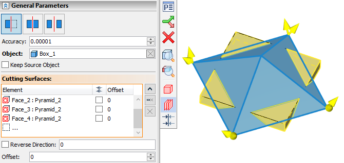
Following steps should be done to create a cut:
1.Sect a command mode (![]() Cut,
Cut, ![]() Split,
Split, ![]() Split with Separation);
Split with Separation);
2.Select an object of cutting (body);
3.Specify, whether the source object should be kept (optional);
4.Select cutting surfaces;
5.Define offsets from selected cutting surfaces (optional);
6.Reverse cutting direction (optional step available in the ![]() Cut mode only);
Cut mode only);
7.Select the resulting parts to be kept (optional step available in ![]() Split and
Split and ![]() Split with Separation modes only);
Split with Separation modes only);
8.Confirm the operation creation ![]() .
.
General Parameters
|
|
General Parameters in the |
General Parameters in |
Upper area of the General Parameters tab of the command parameters window contains buttons for selecting one of the following command modes:
The Accuracy input box is located below. Just like in many other commands, object are being approximated or considered coinciding within this tolerance. Additionally, the Accuracy affects the Offset application. Offsets with absolute values lower than Accuracy are ignored.
Keep in mind that the Offset is measured in millimeters, while the Accuracy is measured in meters.
The body to be cut can be selected in the 3D scene or in the model tree using the following automenu option:
|
<B> |
Select 3D operation |
The selected body is highlighted in green color in the 3D scene and shown in the Object input box of the command parameters window. Selected object can be Cleared ![]() and re-selected using the button located in the right side of the input box. Multiple objects can not be selected. Solid and surface body can be used as an object of cutting.
and re-selected using the button located in the right side of the input box. Multiple objects can not be selected. Solid and surface body can be used as an object of cutting.
The original body is replaced by the result of cutting by default. Enable the Keep Source Object checkbox, if need to keep the original body along with the result of the operation
Cutting surfaces can be selected in the 3D scene or in the model tree using the following automenu option:
|
<C> |
Select intersecting Profile |
Selected surfaces are highlighted in blue color in the 3D scene and are put into the Cutting Surfaces list in the command parameters window. Upon selecting a row in the list, the corresponding surface is highlighted in red color in the 3D scene. You can Expand ![]() , Collapse
, Collapse ![]() , Clear
, Clear ![]() the list or Delete Element from the List
the list or Delete Element from the List ![]() using buttons located on the right side. Upon selecting cutting surfaces, the green highlighting of an object body in the 3D scene is replaced by the dark-yellow highlighting of a cutting result. Surface bodies, worksurfaces, 3D sections, 3D profiles, faces and arrays of all mentioned elements can be used as cutting surfaces. The list of cutting surfaces contains following columns:
using buttons located on the right side. Upon selecting cutting surfaces, the green highlighting of an object body in the 3D scene is replaced by the dark-yellow highlighting of a cutting result. Surface bodies, worksurfaces, 3D sections, 3D profiles, faces and arrays of all mentioned elements can be used as cutting surfaces. The list of cutting surfaces contains following columns:
•Element
Contains an icon of element type, a name of an element and a name of its parent operation.
•![]() Reverse Direction
Reverse Direction
Contains the checkbox of the eponymous option in the ![]() Cut mode. Contains a dash in other modes.
Cut mode. Contains a dash in other modes.
•Offset
By default, an object body is split into parts by an intersection with a cutting surface. However, you can cut the body not by the surfaces itself, but by the equidistant one. Equidistant surface is offset from the selected cutting surface by the value typed into the Offset input box, which is located below the list of cutting surfaces. This value is shown in the Offset column of the list.
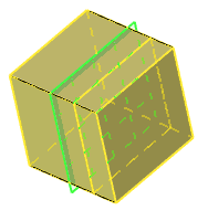
The ![]() Cut mode allows to delete a part of an original body, which lays by one side of a cutting surface. By default, the part to be deleted is selected automatically. You can switch the part to be deleted to an opposite one by enabling the
Cut mode allows to delete a part of an original body, which lays by one side of a cutting surface. By default, the part to be deleted is selected automatically. You can switch the part to be deleted to an opposite one by enabling the ![]() Reverse Direction option for a particular cutting surface selected in the list. The checkbox of this option is available below the list of surfaces as well as in the second column of the list. The input box for this option is also located below the list of cutting surfaces. Enabled checkbox corresponds to the "1" value, disabled - to the "0" value. Values can be also typed in manually or defined using variables. Only whole values are allowed. Any value non equal to zero is counted as "1". This option can also be switched using the following automenu option:
Reverse Direction option for a particular cutting surface selected in the list. The checkbox of this option is available below the list of surfaces as well as in the second column of the list. The input box for this option is also located below the list of cutting surfaces. Enabled checkbox corresponds to the "1" value, disabled - to the "0" value. Values can be also typed in manually or defined using variables. Only whole values are allowed. Any value non equal to zero is counted as "1". This option can also be switched using the following automenu option:
|
<D> |
Switch view direction |
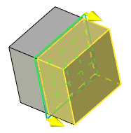
Arrows, pointing to the part of the body to be kept, are shown in the 3D scene for each of the selected cutting surfaces:
If a cutting surface is a workplane and an offset is defined for it, then arrows are shown on an equidistant surface:
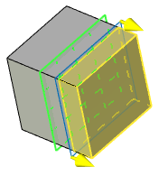
Clicking ![]() on an arrow reverses the cutting direction.
on an arrow reverses the cutting direction.
|
|
Result tab |
Result tab |
In ![]() Split and
Split and ![]() Split with Separation modes the command parameters windows contains the Result tab. If dynamic preview is enabled (by default), this tab contains the list of parts resulting from splitting an original body. Parts are grouped in accordance with resulting bodies (The
Split with Separation modes the command parameters windows contains the Result tab. If dynamic preview is enabled (by default), this tab contains the list of parts resulting from splitting an original body. Parts are grouped in accordance with resulting bodies (The ![]() Split mode always results in a single body, the
Split mode always results in a single body, the ![]() Split with Separation mode results in a separate body for each part). You can fold a section of the list containing part of a particular body by clicking the
Split with Separation mode results in a separate body for each part). You can fold a section of the list containing part of a particular body by clicking the ![]() button, which is located to the left side of a body name. When folded, the button changes to
button, which is located to the left side of a body name. When folded, the button changes to ![]() . Click it again to unfold a section.
. Click it again to unfold a section.
Each part in the list has its own checkbox. All checkboxes are enabled by default. The Keep drop-down list located above the list of parts contains following options:
•All (default)
All parts are kept upon confirming the operation creation. Selecting this option automatically enables checkboxes for all parts.
•Selected
Parts with enabled checkboxes are kept upon confirming the operation creation. Parts with disabled checkboxes are deleted.
•All Excluding Selected
Parts with disabled checkboxes are kept upon confirming the operation creation. Parts with enabled checkboxes are deleted.
The part, which is currently selected in the list, is highlighted in red color in the 3D scene (no matter if it is subjected to deletion or not). The parts to be kept are highlighted in yellow, the parts to be deleted are highlighted in white.
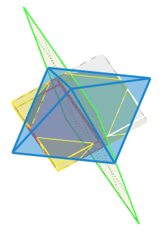
The Unite checkbox is available above the list of parts in the ![]() Split mode, in case when some of the part's checkboxes are not enabled. Enabling the Unite checkbox unites all part to be kept upon confirming the operation creation. In such case, the
Split mode, in case when some of the part's checkboxes are not enabled. Enabling the Unite checkbox unites all part to be kept upon confirming the operation creation. In such case, the ![]() Split result is similar to the
Split result is similar to the ![]() Cut result. However, the
Cut result. However, the ![]() Split provides extended capabilities for selecting the parts to be kept (the
Split provides extended capabilities for selecting the parts to be kept (the ![]() Cut doesn't allow keeping parts, which are not geometrically connected).
Cut doesn't allow keeping parts, which are not geometrically connected).
See also: