Sheet Metal Default Parameters > Common |
  
|
The Common tab of the sheet metal default parameters dialog contains following parameters:

Material thickness.
Defines the thickness of the workpiece that is used by default upon the sheet workpiece creation command.
Bend radius.
Defines the default bend radius used in Bend command.
Part width.
Sets default value for the part width.
Neutral factor (K-Factor).
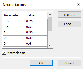
The parameter controls neutral layer factor definition for part bending and unbending. The parameter value can either be entered by the user or defined by the system automatically, based on the table of K-factors versus “bend radius/workpiece thickness” ratio. The K-factor dependency table is stored with the model document. To view or edit the table, use the button ![]() . Upon pressing the button, an additional window Neutral factors opens. This window displays the Neutral factor table of the current document. It represents a tabulated dependency of Neutral factor (the column “Value”) on the ratio “bend radius/workpiece thickness” (the column “Parameter”). The Interpolation flag sets the type of table data interpolation: the set flag means linear interpolation – the Neutral factor linearly interpolated between the tabulated data; the cleared flag means piecewise constant interpolation – the Neutral factor is maintained constant until reaching the next entry.
. Upon pressing the button, an additional window Neutral factors opens. This window displays the Neutral factor table of the current document. It represents a tabulated dependency of Neutral factor (the column “Value”) on the ratio “bend radius/workpiece thickness” (the column “Parameter”). The Interpolation flag sets the type of table data interpolation: the set flag means linear interpolation – the Neutral factor linearly interpolated between the tabulated data; the cleared flag means piecewise constant interpolation – the Neutral factor is maintained constant until reaching the next entry.

The current table can be exported into a textual file by pressing the button Save.
The Load button allows you to change the table by loading new data from the user-created text file *.tnf of the following format: the first line in the file should specify the type of interpolation: “Interpolation” - linear, “Table” - tabular. Other lines contain the table data – the “bend radius/workpiece thickness” ratios and the respective Neutral factor values. Table data can be recorded in various ways- in one row or in several, spaces or tabs can be used as delimiters. For example, the default table is written as follows:
Interpolation
0.5 0.25
0.8 0.3
1 0.35
2 0.37
3 0.4
4 0.41
5 0.43
10 0.47
12 0.5
Once loaded from a file, the table is stored in the document of the current model and is further used in model manipulations.
Minimum gap.
The parameter defines the width of a cut when creating operations with sheet metal. Defines the Reduce cutting option. More info available in the Flange section.
Bend/unbend face completely.
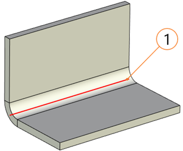
This parameter is important when performing operations on the sheet metal of certain geometry (for example, when it is required to bend the sheet body with a cut along the specified line). When this parameter is enabled, the entire body along the selected line will be bent without violating the construction logic. The parameter defines the setting/removal of the default flag for the Bend face completely option in the dialog for creating bending operations.

1 - Bend Line
Check self-intersections.
This parameter is important when creating the Bend operation. It allows you to monitor self-intersection of bent sheet faces. When the flag is set, the system will not create bend that intersects with the source body. Defines the default setting/clearing of the flag for the Check self-interactions option in bending operations.
Activate manipulator.
If the flag is set for Flange, Hem, Jog operations, the mode of defining a length using manipulator is activated automatically, after selecting an edge or profile.
Simplify geometry.
The parameter removes the edges that are formed as a result of flanges, hems, bridge bends, and other sheet metal operations construction.