3D Weld Geometry Types: Compound |
  
|
A compound 3D weld may be created using one of the following methods:
•By Edges, 3D Paths, 3D Profiles, and Operations;
Compound weld is not available in the list of weld geometry types, if a non-standard weld type is used.
By Edges, 3D Paths, 3D Profiles, and Operations
A 3D weld created on edges, 3D paths, 3D profiles, and operations, can be used in the cases when the required appearance of the weld cannot be achieved by building it on the model faces. It serves to indicate that some existing 3D model elements represent welds. The supply more information with the created composite weld, you can specify, what parts it connects. Please note that such a 3D weld cannot be nonstandard.
When the 3D weld is created, no additional “cosmetic” weld body is created in the 3D scene. You can still “see” such a weld – as you select it in the welds window, the respective 3D objects will be highlighted in the 3D scene.
If necessary, you can manually assign the “WeldMaterial” material to the body representing a 3D weld.
A 3D weld created on edges, 3D paths, 3D profiles, and operations, is entered into the table of welds along with other types of welds. The length of a composite weld is determined in the automatic calculation mode as the sum of the perimeters or lengths of all 3D model elements that are involved in it, except bodies (operations). The bodies that are involved in a composite weld, are not accounted for when automatically calculating its length.
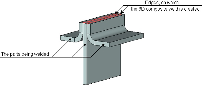
As an example, consider creating a flange-face weld. Suppose, we need to create a weld that connects three parts (see the figure below). Neither the fillet nor the butt 3D weld is suitable in this case. We will therefore create a 3D weld on two edges, and will additionally specify what bodies must be connected by this weld.

A 3D weld can be created based on a set of already existing 3D welds. Such a weld cannot be nonstandard. Just like in the previous case, no additional body is created in the 3D scene when such a 3D weld is created.
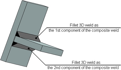
As an example of creating such a weld consider creating in T-FLEX CAD a two-sided Tee-weld. A Tee-weld can be imitated by a pair of fillet welds. To make this pair of welds work as a single weld in the future, you need to additionally join them into one weld.

To add more information to the created composite weld, you can specify, what parts it connects.
The length of the composite weld in the automatic calculation mode is determined as the sum of all 3D welds that it includes. The properties of a composite weld created from a set of 3D welds are determined by the type specified for this composite weld. The parameters of the source welds are ignored. Please also note that the table of welds generally includes both the source 3D welds and the resulting weld, which is based on them. To avoid duplicates, we recommend using nonstandard 3D welds as the source welds. In this case, those will not be entered in the welds table.