Parameters of Breaks of Projections and Drawing Views |
  
|
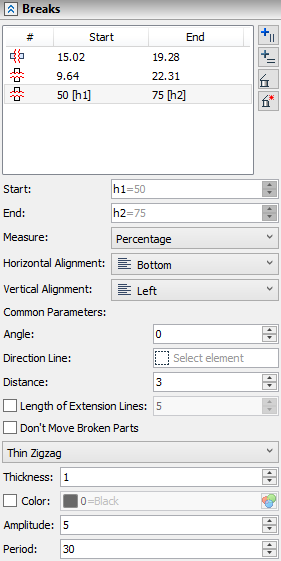
Breaks of a current projection are listed in the Breaks tab of the parameters window.

You can select breaks in the list by clicking ![]() . You can
. You can ![]() Add Vertical Break,
Add Vertical Break, ![]() Add Horizontal Break,
Add Horizontal Break, ![]() Delete the selected break or
Delete the selected break or ![]() Delete All breaks using buttons located to the right of the list. New breaks may also be added using corresponding automenu options. The selected break may also be deleted using <Del> button. For each break the list displays a break type icon (
Delete All breaks using buttons located to the right of the list. New breaks may also be added using corresponding automenu options. The selected break may also be deleted using <Del> button. For each break the list displays a break type icon (![]() - vertical,
- vertical,![]() - horizontal) and following parameters:
- horizontal) and following parameters:
•Start
Position of a boundary closest to the origin.
•End
Position of a boundary farthest from the origin
Values of the Start and End parameters are defined, when using the manipulators of break boundaries. Alternatively, you can type in values into Start and End input boxes below the list. These input boxes contain parameters of a break currently selected in the list. Values can be defined using variables; then names of variables are displayed in the list in square brackets after numerical values. Unit of measurement for these parameters are defined by the selected Measure option. Origin and direction of measurement are defined by the alignment options (see further).
Below the Start and End input boxes there are following parameters, common for all breaks in the list:
•Measure
Units of breaks positions measurement. Following options are available in the drop-down list:
oPercentage
Position is measured in percents of projection's bounding box dimensions.
oIn Model Units
Position is measured in absolute length units set in the Document Parameters for the current drawing page (by default: inches for ANSI drawing, millimeters for ISO drawings).
•Horizontal Alignment
Defines origin and direction of horizontal breaks position measurement. Following options are available in the drop-down list:
o![]() Bottom
Bottom
Position is measured upwards from bottom boundary of projection.
o![]() Center
Center
Position is measured upwards from center of projection.
o![]() Top
Top
Position is measured downwards from top boundary of projection.
•Vertical Alignment
Defines origin and direction of vertical breaks position measurement. Following options are available in the drop-down list:
o![]() Left
Left
Position is measured to the right from left boundary of projection.
o![]() Center
Center
Position is measured to the right from center of projection.
o![]() Right
Right
Position is measured to the left from right boundary of projection.
•Angle
Breaks are either horizontal or vertical by default. In order to make them sloped, you should define a slope angle. Angle is defined either by typing a value into the Angle input box, or using automenu option.
•Direction Line
When editing breaks, you can define a brakes angle by setting the arrow of base point marker parallel to a construction line. In such case, a value in the Angle input box becomes non-editable, and the Direction Line input box indicates an icon and a name of a selected line. You can ![]() Clear the selection using the button located in the right side of the box. Clearing the selection restores the zero angle.
Clear the selection using the button located in the right side of the box. Clearing the selection restores the zero angle.

•Distance
Distance between adjacent broken parts.
•Length of Extension Lines
This checkbox is disabled by default. In such case, break lines are drawn only through bodies on projections and only between outermost graphic lines on drawing views not linked to the 3D model. Enabling this checkbox extends breaks lines on each side at a distance set in the input box located to the right of the checkbox.
•Don't Move Broken Parts
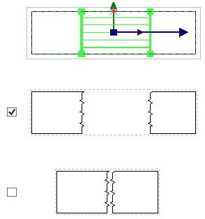
This checkbox is disabled by default. In such case, broken parts of projection are placed at the distance from each other set in the Distance input box. Enabling this checkbox makes broken part stay in initial positions.

•Break lines type
You can select one of the following line types in the drop-down list: Thin Zigzag, Thin Waves, Thin Dashdot, No. Selecting the No type disables break lines display.
|
|
|
|
Thin Zigzag |
Thin Waves |
Thin Dashdot |
No |
T - Period, A - Amplitude, D - Distance |
|
||
Keep in mind, that the more complex the break line is, the longer it takes to regenerate a broken view.
•Thickness
Thickness of break lines in absolute length units set in Document Parameters for the current drawing page (by default: inches for ANSI drawing, millimeters for ISO drawings).
•Color
This checkbox is disabled by default. In such case, break lines are colored in black. Enabling this checkbox allows to select a color from the drop-down list, or from the catalog, as described in the Color section.
•Amplitude
The geometric meaning of this parameter is shown in the figure above. This parameter is not available for the dashdot line.
•Period
The geometric meaning of this parameter is shown in the figure above. This parameter is not available for the dashdot line.