Breaks of 2D Projections and Drawing Views |
  
|
Breaks of 2D Projections and Drawing Views |
|
When drawing long parts, it is often necessary to limit the part view to a certain portion for keeping the drawing compact. T-FLEX CAD provides tools for creating projections, drawing views and detail vies with breaks. Breaks can be added for all types of projections, except for the local section view and the unfolding section view.
Pay attention to the following details when working with broken views:
•When attaching a radial dimension or both legs of a linear dimension to lines of such projection or their children, the system automatically adjusts the dimension to obtain the true value.
•If the broken view was created in an already existing projection (when editing it) with some elements attached to it, such as dimensions, then these elements may get lost due to changes in the projection topology after creating the broken view.
If you create a new projection by a projection with break, a break from the main projection will be copied to the dependent projection.
The breaks are created only in two orthogonally related directions. The number of breaks in either direction is unlimited. A break is defined by a rectangular area. Two of its boundaries are determined by the extents of the projection, while the other two are defined by the user using the mouse and the appropriate options.
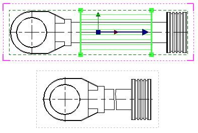
The rectangular area of the break is hatched by the lines at the time of creating and editing, the lines direction indicating the direction of the view reduction (orthogonal to the breaking lines).
The following diagram shows an example of a projection with a broken view.
Topics in this section:
•Adding Breaks, when Creating Projections and Drawing Views
•Excluding Elements from Breaks
See Also:
•Exclusions for Elements of 2D Projection