Projection By Projection |
  
|
A projection of this type can be created using the following automenu option of the 2D Projection command:
|
<7> |
By Projection |
First, the source 2D projection is to be specified in order to use its parameters for the projection being created. The source projection is selected using the following automenu option, which is active by default:
|
<V> |
Select source Projection to specify Parameters |
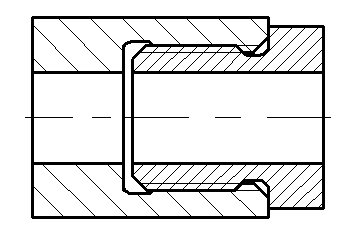
The new 2D projection will match the source one in its position, orientation, and the use of broken views. The rest of the projection parameters can be edited: you can change the list of the objects to be projected and the applied sections, the projecting (mapping) method, available line styles, and hatch parameters.
The newly created 2D projection is automatically assigned the priority which is by five points greater than the source projection. In addition, the flag Create Outlined Area is set in the parameters of the new 2D projection.
This method of creating a 2D projection can be used to construct projections of threaded connections where both the “screw” and the “nut” of the connected pair are sectioned. The thread lines of both the “screw” and the "nut" will be overlapped on the projections in which both parts are simultaneously sectioned. To insure the correct appearance of a threaded connection, what one can do is originally create the projection of the sectioned “nut”, and then create another 2D projection based on the first one, where you specify the “screw” only in the “to be projected” list.

See Also:
•Algorithm of Creating 2D Projection
•General Parameters of 2D Projection
•Position of 2D Projection on Drawing
•Additional Parameters of 2D Projection
•3D Model Elements on 2D Projection
•2D Projection by External Model
•Parameters of Sections on 2D Projection