Arbitrary View |
  
|
The command can be called in one of the following ways:
Icon |
Ribbon |
|---|---|
|
Draw > Projection > Arbitrary View Sheet Metal (2D) > Draw > Arbitrary View |
Keyboard |
Textual Menu |
<3ZJ> |
Draw > 2D Projection > Arbitrary View |
It is also available as option in the 2D Projection command:
|
<8> |
Arbitrary View |
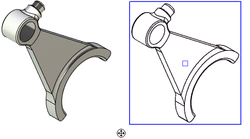
This type of projection allows you to set any arbitrary projecting direction.
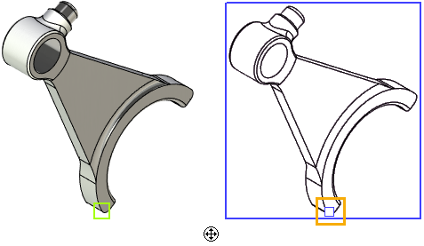
First, upon calling the command, you need to define the position of the projection on the drawing. In addition to methods of defining projection's position common for all projection types, the arbitrary view allows you to coincide the projection's LCS origin with any arbitrary 3D point. Such point can be selected using the following automenu option:
|
<N> |
Select Point for superposing with the attachment point |


Next, you should define a projecting direction. Default projecting direction is defined by the position of active camera in 3D window at the moment of calling the command.
Another projecting direction can be set by one of the following means:
•Select projection plane
The projecting direction will be defined by the normal to this plane. To select a plane, use the option:
|
<F> |
Select Plane to set view direction |
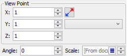
•Define the viewing point in the parameters window
It can be defined using coordinates or by selecting one of the standard or custom views. The coordinates of the view direction can be defined in the parameters window. The X, Y and Z are entered in the respective input boxes of the end point of the direction vector. The start point of the vector is the origin of the global coordinate system.

Use the following automenu option if you want to restore the default projecting direction:
|
<K> |
Cancel setting of view direction. |
See Also:
•Algorithm of Creating 2D Projection
•General Parameters of 2D Projection
•Position of 2D Projection on Drawing
•Additional Parameters of 2D Projection
•3D Model Elements on 2D Projection
•2D Projection by External Model
•Parameters of Sections on 2D Projection