Parameters of Sections on 2D Projection |
  
|
The parameters for controlling the sections that are grouped in the Sections tab of the parameters window.
Selecting 3D Sections to be applied
Names and icons of applied sections are displayed in the list Use Sections. Section can be selected in the list using ![]() . The list can be managed using Expand
. The list can be managed using Expand ![]() , Collapse
, Collapse ![]() , Delete Element from the List
, Delete Element from the List ![]() and Clear
and Clear ![]() buttons located to the right.
buttons located to the right.
In order to add 3D sections to the list, activate the following automenu option, or click ![]() the last row of the list (the one marked with ...):
the last row of the list (the one marked with ...):
|
<O> |
Select 3D Sections to apply |
In result, filters for selecting 3D sections become active on the filter toolbar, so you can select desired sections by clicking ![]() them in 3D scene or in model tree.
them in 3D scene or in model tree.
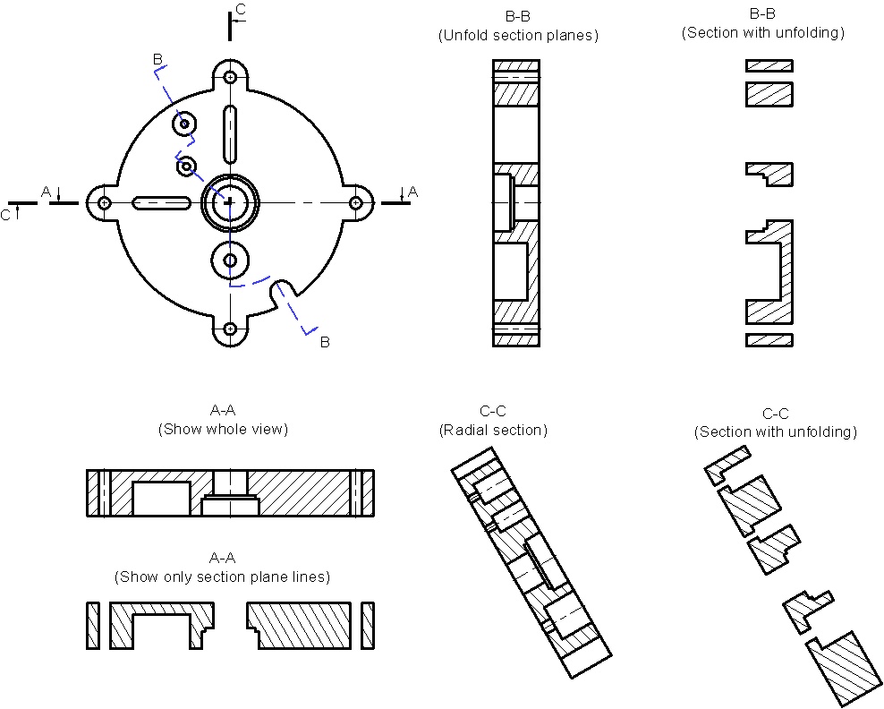
The type of the projection created by using sections can be selected from the drop-down list: Section View, Only Section Planes, Unfold/Radial Section and Section with Unfolding.
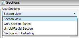
Unfolding can be done only if a composite section was used (a one containing multiple segments).
The option Unfold/Radial Section can work in one of two modes. This depends on what type of multiple-point section is used in the case. If a multiple-point section is composed of all straight segments, the whole section will be fully unfolded. If at least one segment of a multiple-point section is a circular arc, then the radial section mode turns on. In this case, all arcs are skipped when unfolding the section.
The option Section with Unfolding always creates full section unfolding, even when the section contains circular arcs.
Selecting elements to be cut by section
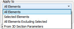
Selected sections can be applied to all projected elements or to particular elements only.
The method of applying sections can be selected in the Apply to drop-down list. The available options are All Elements, Selected Elements, All Elements Excluding Selected, From 3D Section Parameters. The list of elements for Selected Elements and All Elements Excluding Selected methods is located below.
The All Elements option is set by default. The elements list is empty for this option.
When choosing the From 3D Section Parameters option the section application rules are taken from the 3D section parameters. The elements list in projection's parameters is empty for this option.
It is possible to specify beforehand that a 3D fragment will NOT be cut by a section, when creating a section view of an assembly, if some conditions are met. These conditions can be set in document parameters (Document Parameters > Document > 3D Fragment > Sections) and is usually used in the libraries of standard parts.
The list below contains names and icons of elements, which the sections are applied (for the Selected Elements option) or not applied to (for the All Elements Excluding Selected option). Elements can be selected in the list using ![]() . The list can be managed using Expand
. The list can be managed using Expand ![]() , Collapse
, Collapse ![]() , Delete Element from the List
, Delete Element from the List ![]() and Clear
and Clear ![]() buttons located to the right.
buttons located to the right.
In order to add elements to the list, activate the following automenu option, or click ![]() the last row of the list (the one marked with ...):
the last row of the list (the one marked with ...):
|
<Ctrl>+<O> |
Select Operation to which 3D Section will be applied |
In result, filters for selecting bodies, operations an welds become active on the filter toolbar, so you can select desired elements by clicking ![]() them in 3D scene or in model tree.
them in 3D scene or in model tree.
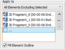
The contextual menu of hatches on cut elements contains the following item: Projection > Don't Apply Section. Upon calling this command, the operation, for which the cut hatch was created, will be added to the list of the operations that shall not be subjected to sectioning in the given projection (the All Elements Excluding Selected option is applied automatically). After that, the projection will be automatically rebuilt.
In the following example, two sections are created, both based on the main view. In the first case, the section was applied to the shroud only, while in the second case – to all bodies.
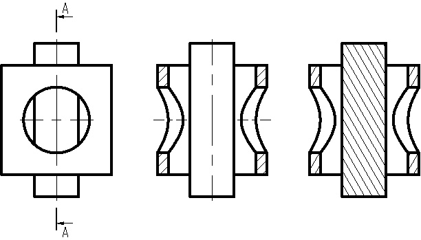
The following checkbox is available below the list of elements:
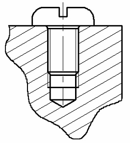
Fill Element Outline.
This setting helps correctly draw threaded connections in which elements penetrate each other (due to the specifics of this type of connection). Additionally, some elements of the threaded connection (for example, the standard elements) can be exempted from section.
Hatch parameters for cut elements
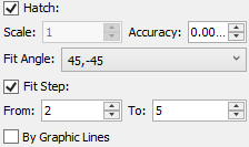
Hatch
This parameter defines, whether the cut elements will be hatched or not.
Scale
The hatch scale.
Accuracy
This is the accuracy of tracing the hatch contour. Adjusting this parameter helps in complicated cases, when the system cannot hatch the contour under the previously specified accuracy.
Fit Angle
Sets the choice of automatic hatch angle definition for crosscut parts. The drop-down list provides two choices: 45, -45 only and 30, 45, 60, -30, -45, -60.
Fit Step
Sets the upper and lower limits on the values, within which the system automatically picks up a hatch step. The step size is determined relative to the area of the hatch contour.
By Graphic Lines. This option is available only for projection of the type “Precise (Image Lines”)
When this checkbox is enabled, the hatch on cuts/sections is formed by graphic lines of the projection, when it is disabled – by faces which appear on the projected body as a result of applying 3D section. By default this checkbox is disabled, i.e., the hatches are created by the faces of the section (since the graphic lines on the projection do not always form a closed contour due to loss of accuracy while projecting). It is recommended to enable this checkbox if the hatch being created will be used later for construction of 3D profile or local section view.
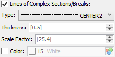
The Lines of Complex Sections/Breaks checkbox is enabled by default in the lower part of the Sections tab. In result, special lines are drawn on projection indicating the jogs of cutting plane. Parameters of such lines can be customized either below the checkbox, or in the Lines tab of the command's parameters window.

Managing hatch parameters in cuts and sections
The drawing standards require that all cut or sectioned parts are hatched in a certain way. If the material the part is made of requires hatching by a special pattern, then the appropriate pattern hatch type must be set in the material properties. In all other cases, the material is hatched in the sectioned areas by the repeating lines with a certain slope and step. If multiple bodies are involved in a section, then the hatch slope and step must differ across them. When creating a cut or sectioned for the first time, the system automatically picks different hatch parameters (slope angle and step) for different parts. Note also that the hatch parameters that were once picked for a certain part (operation) are automatically remembered in the model, and the same hatch parameters will be used for the same part in any cuts or sections on other views.
Those hatch parameters are stored together with the original operation and are propagated on child operations, whenever those have the flag set, Attributes from Source Operation.
However, user can edit hatch parameters. Upon confirming hatch parameters change, the system asks to Save Hatch Parameters in source Operation in order to use in other Section Views:
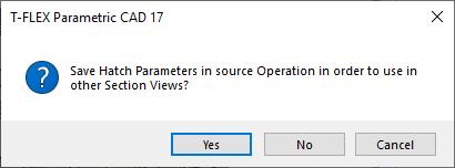
This dialog appear only if changes are made using the hatch parameters dialog and the Hatch is used both as initial and final filling methods.
If you answer Yes, new hatch parameters are saved in model and will be used as default hatch for this part on all sections. If you answer No, new hatch parameters are only applied to current projection.
To revert the individually specified hatch parameters back to the parameters assumed from the 2D projection, one would need to right-click this hatch ![]() and in the coming up context menu select the item Properties from Projection.
and in the coming up context menu select the item Properties from Projection.
See Also: