Lines of 2D Projection |
  
|
Lines of 2D Projection |
|
On the Lines tab of the ![]() 2D Projection command's parameters window, you can change the parameters of the projection lines separately for each 3D construction element, body or fragment.
2D Projection command's parameters window, you can change the parameters of the projection lines separately for each 3D construction element, body or fragment.
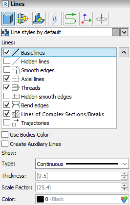
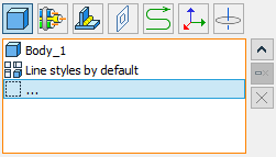
The upper part displays a list of selected elements for which you can change the line parameters.
You can select the elements for which you want to change the lines by clicking on the ... entry in the list in the parameters window.
The ![]() Line style by default entry allows to customize line styles for the rest of the elements except the ones specifically selected above.
Line style by default entry allows to customize line styles for the rest of the elements except the ones specifically selected above.
In the center is a list of projection line categories. To display the lines of the selected category on the projection, set the flag to the left of the category name.


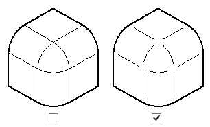
The same projection with different line categories enabled
1 - Basic lines
2 - Basic lines + Smooth edges
3 - Basic lines + Hidden lines
The line parameters available for editing are displayed at the bottom and depend on the selected category.
You can select several lines at the same time and set general parameters for them.
Use bodies color. When this option is enabled, the color of all projection lines and hatches in the section is determined by the color assigned for projected operations. The body color is used when displaying in tonal mode.
Type. From the drop-down list, you can select the line type for the selected category.
Thickness. Sets the thickness of the lines
Scale factor. Lets you set the amount of strokes for non-solid lines.

Color. You can select a color from the drop-down list or specify the number of the desired color.
Line categories:
•Basic lines. Allows you to set the parameters of the Basic lines.
•Hidden lines. The parameters of this group control the presence and parameters of displaying hidden lines on a 2D projection.
•Smooth edges. Smooth fillets of faces can be shown on the projection (when no sharp corner is formed at the seam). This group of parameters controls the rendering of smooth fillets, sets the display method (type, color, etc.) of the graphic lines used for this. Upon selecting the Smooth Edges in the list of categories, additional option appears below the line parameters:
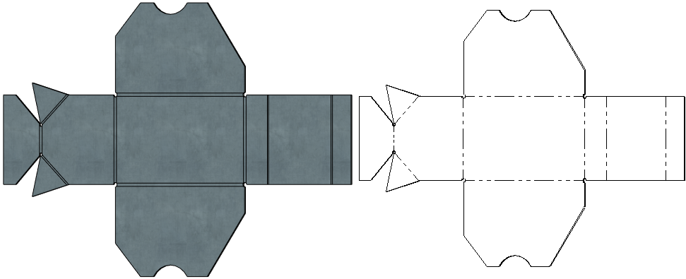
oShorten Line. The effect is shown in the picture below.
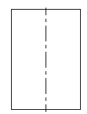
•Axial lines. When projecting surfaces of revolution (cylinder, cone, torus), you can automatically add axis lines. In the case when the body has several surfaces of revolution. Axial lines checkbox also controls the drawing of the bend axes on the projections of bodies obtained by the Unbend operation. Upon selecting the Axial lines in the list of categories, additional options appear below the line parameters:
oUnite (enabled by default). This option is useful, when projecting several rotated surfaces. It helps to avoid duplicating axes.
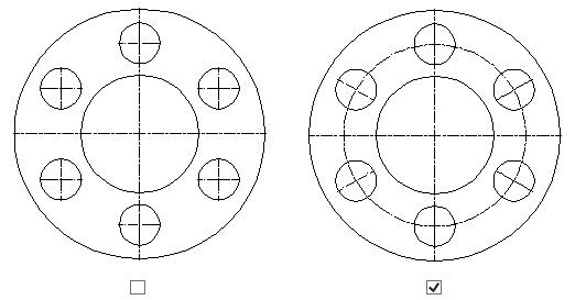
oRadial Axes (enabled by default). This option is useful, when projecting holes that are placed along a circle. The effect is shown in the picture below.
•Threads. When creating 2D projections, the threads present in the model are automatically recognized. When this option is enabled, thread designation lines are created in cases when the thread is visible in this projection from the front, from the side, or the plane of the cut coincides with the thread axis. When dimensioning from such an image of the thread, the system automatically substitutes the required designation. The data for the designation is taken from the parameters of the thread creation operation. Upon selecting the Threads in the list of categories, additional input box appears below the line parameters:
oMinimum Thread Height. Minimal distance between thick and thin lines of a thread on a drawing. Measured in units set for a Page in the Document parameters (by default, it's millimeters for ISO documents and inches for ANSI documents).
Also see the Thread Display on 2D Projections section.
•Hidden smooth edges. This category includes smooth mates that are invisible on the projection.
•Bend edges display bend lines in projections of sheet metal parts.
•Lines of Complex Sections/Breaks. Used to draw visible edge segments that were obtained by intersecting projected bodies with planes of stepped sections orthogonal to the projection direction. parameters of these lines may also be customized in the Sections tab.

•Trajectories. Used in exploded views.
The Lines tab allows to adjust the parameters of the lines (for more details, see the section 2D Projection Parameters).
It also contains the Create Auxiliary Lines checkbox. Enabling this checkbox makes auxiliary all lines of the projection.