Position of 2D Projection on Drawing |
  
|
You can change a position of a projection on a drawing page. Methods of positioning in the command standby mode are different from methods of positioning during projection's creation or editing.
During projection's creation or editing you can snap it to an arbitrary drawing element or link to another projection via a projection link.
Positioning a projection during its creation and editing
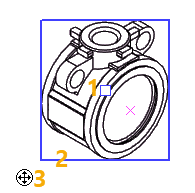
Upon defining a basic set of mandatory projection's parameters (in case of a standard projection, it is enough to select its type), a projection's preview appears in a drawing. The preview contains ![]() projection center marker,
projection center marker, ![]() translation manipulator and actual boundaries of the projection. Actual boundaries displayed during projection's creation and editing differ from boundaries displayed in other cases (see Boundaries of 2D Projection section). By default, a projection is placed in the center of the page. You can move it using following methods:
translation manipulator and actual boundaries of the projection. Actual boundaries displayed during projection's creation and editing differ from boundaries displayed in other cases (see Boundaries of 2D Projection section). By default, a projection is placed in the center of the page. You can move it using following methods:
•Drag&Drop
Move the cursor over any point within projection boundaries (blue frame) or over the translation manipulator ![]() , then press and hold
, then press and hold ![]() . While
. While ![]() is held pressed, the projection follows the cursor. Place the projection in a desired position by moving the cursor and release
is held pressed, the projection follows the cursor. Place the projection in a desired position by moving the cursor and release ![]() .
.
•Point&Click
Move the cursor over any point within projection boundaries (blue frame) or over the translation manipulator ![]() , then click
, then click ![]() . The projection starts following the cursor. Place the projection in a desired position by moving the cursor and click
. The projection starts following the cursor. Place the projection in a desired position by moving the cursor and click ![]() again.
again.
Instead of the first click ![]() , you can use the following automenu option, which also makes the projection follow the cursor:
, you can use the following automenu option, which also makes the projection follow the cursor:
|
<M> |
Change Projection Placement |
When creating projections of some types, the preview may follow the cursor right from the start. Clicking ![]() fixates the projection.
fixates the projection.
When creating three standard views or standard view set, first you have to click ![]() a projection, which have to be re-positioned. Only then the projection center marker and translation manipulator appear, the boundaries get highlighted in blue, and the projection can be moved using one of the methods described above.
a projection, which have to be re-positioned. Only then the projection center marker and translation manipulator appear, the boundaries get highlighted in blue, and the projection can be moved using one of the methods described above.

1 - projection center marker,
2 - projection boundaries,
3 - translation manipulator
Snapping a projection to an arbitrary drawing element
When moving a projection using any of the methods described above, you can create a link between position of the projection and position of another drawing element, such as 2D node, key point of drawing line, intersection of construction lines (selecting an intersection automatically creates a connected 2D node there). While the projection follows the cursor, snap its center marker to a desired element using object snappings and finish the translation by pressing or releasing ![]() (depending on the method of translation). The link will be created, so the subsequent changes in position of the linked element will lead to corresponding changes in position of the projection.
(depending on the method of translation). The link will be created, so the subsequent changes in position of the linked element will lead to corresponding changes in position of the projection.
A projection can be linked to another projection via a projection link. In such case, the position of the current projection (linked view) depends on the position of another projection (main view). The link prevents a linked view from moving independently in any direction, except the direction along link lines. Link lines are invisible lines, that connect the same points of model on different projections.
A linked view can be moved along link lines in the same way as described above for free view re-positioning. The only difference is that the projection will follow the cursor only in one possible direction.
In order to move a linked view in other directions, you have to move its main view.
For a single standard view a projection link can be set using the following automenu option:
|
<F> |
Select main view to define projection link |
Upon activating this option, you have to click ![]() an existing projection, which will define the position of the current projection. The same option can be used for re-linking to another main view.
an existing projection, which will define the position of the current projection. The same option can be used for re-linking to another main view.
When creating three standard views or standard view set, one of the created projections is the main view, while others are its linked views. In such cases, links are created automatically. When editing such linked views, you cannot select another main view.
For arrow views, as well as for sections views/cuts based on cutting lines, the main view is the one that contains the linked cutting line/view arrow. Section views/cuts based on 3D sections are linked to the LCS of the current drawing page and can only be moved along one of its axes.
A projection link (regardless of whether it's set manually or automatically) can be broken using the following option:
|
<K> |
Set / Break link with projection |
Upon breaking a link, the information on the used main view is kept, so you can restore the link by applying the same option again, without re-selecting the main view.
Positions of some projections (local section, projection by projection) are fully defined by positions of parent projections. In such cases, child projections cannot be moved independently.
Re-positioning a projection in the command standby mode
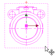
When some of the projections is active, neither the active one, nor others cannot be moved. When none of the projections are active, move the cursor over a projection, which has to be moved. The projection will be highlighted and the translation icon will appear near the cursor. While the icon is displayed, the projection can be dragged with mouse using the standard move with translation mechanism. Unlike re-positioning a projection within its creation and editing commands, snapping a projection to other drawing element, when moving with translation, doesn't create an associative link, i.e. subsequent changes in position of a snapping element do not affect the position of the projection.

See Also:
•General Parameters of 2D Projection