Local Section View in 2D Projection Command |
  
|
A local section view can be created using the following option in the 2D Projection command:
|
<4> |
Local Section View |
The boundaries of the local section view are defined by the hatch contour. You can use an existing hatch or create a new one during creating a view.
Use the following automenu option to select an existing hatch:
|
<1> |
Select Hatch as boundary of local section view |
Upon completing creation of the local section, the hatch becomes invisible, while overlapping a portion of the main projection. The lines of the local section will be drawn with higher priority, than those of the hatch and the main projection.
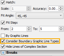
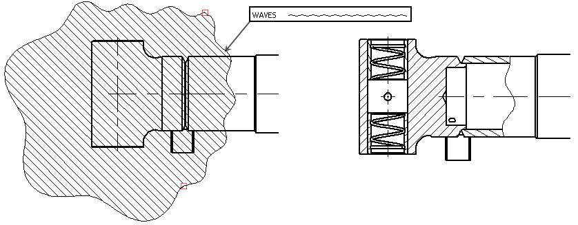
By default, type of graphic lines outlining the selected hatch can be taken into consideration when defining the contour of the local section view. For example, if the hatch outline was set as waves, the contour of the local section view will also be bounded by waves. This option can be disabled by disabled by disabling the Consider Boundary Graphic Line Types checkbox, which is available at the bottom of the Sections tab of the parameters window. With the checkbox disabled, the contour of the local section view will follow the blue lines displayed upon selecting a hatch, regardless of line type.
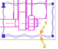
1 - Contour considering line type
2 - Contour not considering line type
Use the following automenu option to create a new hatch directly in the Local Section View command:
|
<6> |
Create Hatch by Spline |
Upon selecting this option, click ![]() on a drawing sheet.
on a drawing sheet.
If cursor is outside boundaries of any existing projections at the moment of clicking ![]() , then the projection selection dialog appears. Upon selecting a projection, the system launches the spline creation command.
, then the projection selection dialog appears. Upon selecting a projection, the system launches the spline creation command.
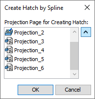
If cursor is inside boundaries of any existing projection (the projection gets highlighted in this case) at the moment of clicking ![]() , then the spline command will be launched instantly for creating a spline on such projection:
, then the spline command will be launched instantly for creating a spline on such projection:
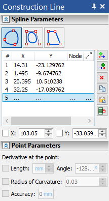
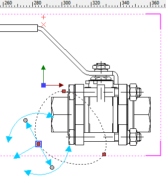
Upon finishing spline creation, the system returns to the 2D Projection command, automatically creates an invisible hatch by the spline, and selects this hatch as a section's contour.
Name and icon of the selected hatch are displayed in the Local Section View box in the Sections tab of the parameters window. You can ![]() Clear the selection, if necessary, using button located at the right side of the box.
Clear the selection, if necessary, using button located at the right side of the box.

If the spline was created in a wrong configuration, you can cancel its creation using the following automenu option:
|
<G> |
Reset Created Hatch |
Next, you should define the position of the cutting plane. The plane normal automatically coincides with the viewing direction of the main projection – the one used for creating the local section view. The plane passes through a user-selected point. You can select either a 3D point in 3D scene, or a 2D point on another 2D projection, using one of the following automenu options:
|
<3> |
Select Point, defining cutting plane position |
|
<2> |
Select 2D Node on other Projection, defining section position |
Depending on the selected option, filters for selecting ![]() 2D or
2D or ![]() 3D points become active in the filter toolbar. Selecting a 2D point other than 2D node results in automatic creation of a 2D node at the selected point.
3D points become active in the filter toolbar. Selecting a 2D point other than 2D node results in automatic creation of a 2D node at the selected point.
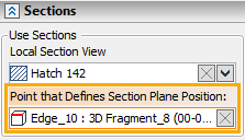
Name and icon of the selected point are displayed in the Point that Defines Section Plane Position box in the Sections tab of the parameters window. You can ![]() Clear the selection, if necessary, using button located at the right side of the box. In order to re-select a point, activate one of the aforementioned options again or click the point's box in the parameters window. Clicking the box activates the 3D point selection option.
Clear the selection, if necessary, using button located at the right side of the box. In order to re-select a point, activate one of the aforementioned options again or click the point's box in the parameters window. Clicking the box activates the 3D point selection option.
Position of a section in a drawing
The local section view is automatically tied to the projection on which it was created. However, this tie needs to be broken in some situations, in order to attach the local view to the drawing at a different location. The option to break the tie is:
|
<K> |
Set / Break link with projection |
Once the tie is broken, the following option common for most projection types is available:
|
<5> |
Move Local Section View |
Upon activating this option, you can place the local section anywhere in the drawing in the same way, as when placing projections of other types.
When creating a local section view, we recommend selecting specific model elements to be projected. Selecting the elements that actually fall in the area of the local section view speeds up regeneration of the projection.
Selecting elements to be cut by section
By default, a section cuts all elements within its contour. If necessary, you can apply a section to particular elements only. Method of applying a section and elements for the section to be applied to are selected in the same way, as when applying 3D sections to 2D projections.
Hatch parameters are set in the Sections tab of the parameters window (see the Parameters of Section on 2D Projection section).
Along with tools and parameters described above, when creating or editing a local section in this mode, you can use other tools and parameters common for all types of 2D projection.
Local Section View in 3D Model Tree
Local section views created via this method are displayed in 3D model tree in the same way, as views created via the application mode of the Local Section View command.
See Also:
•Local Section View > Within Projection
•Local Section View > Application
•Algorithm of Creating 2D Projection
•General Parameters of 2D Projection
•Position of 2D Projection on Drawing
•Additional Parameters of 2D Projection
•3D Model Elements on 2D Projection
•2D Projection by External Model
•Parameters of Sections on 2D Projection
•Breaks of 2D Projections and Drawing Views