Spline and Polyline. 2D Constructs |
  
|
The command can be called in one of the following ways:
Icon |
Ribbon |
|---|---|
|
Draw > Construct > Spline Workplane > Construct > Spline |
Keyboard |
Textual Menu |
<SP> |
Construct > Spline |
Splines are drawn basing on a set of points. If the location of points is changed, the spline shape changes too.
Upon calling the command you have to select a type of spline to be created. Type selection is performed via the buttons in the Spline Parameters tab of the parameters window or via the hotkey combinations mentioned below. There are following types available:
|
<Shift>+<H> |
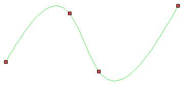
Spline |
The spline goes through given control points.
|
<Shift>+<J> |
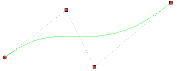
Spline by Polyline (NURBS) |
A polygonal line goes through control points, and the spline is based on such line.
|
<Shift>+<K> |
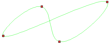
Closed Spline |
A closed spline goes through given control points.
|
<Shift>+<L> |
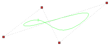
Closed Spline by Polyline (Closed NURBS) |
A closed spline based on polygonal line, where latter goes through control points.
|
<Shift>+<G> |
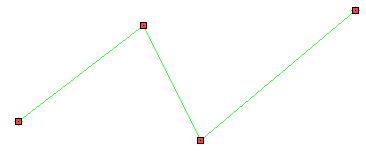
Polyline |
A first degree spline.
|
<Shift>+<F> |
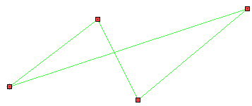
Closed Polyline |
A closed first degree spline.
While creating and editing a spline, you can change its type at any moment.
The spline drawing command functional in construction lines and in a sketch is practically identical. But there are some minor differences.
•Object snapping doesn't recognize control points of the construction spline.
•A node can be snapped to construction spline, with specifying a relative position along the spline.
•The parameters dialog ![]() of a construction spline parameters is different from the one of a sketch spline.
of a construction spline parameters is different from the one of a sketch spline.
Choose one of the aforementioned spline types. Specify the location of control points with ![]() . The points can be bound to 2D nodes. The location of the points can be defined using object snapping. Upon specifying a first control point, the dynamic preview of the spline appears on the screen. The last point of the spline follows the cursor, so the preview changes accordingly. When creating a spline by polyline, a preview of a polyline is shown along with a preview of a spline.
. The points can be bound to 2D nodes. The location of the points can be defined using object snapping. Upon specifying a first control point, the dynamic preview of the spline appears on the screen. The last point of the spline follows the cursor, so the preview changes accordingly. When creating a spline by polyline, a preview of a polyline is shown along with a preview of a spline.
Coordinates and other parameters of the specified points, as well as geometrical parameters of the spline as whole, are shown in the parameters window (see the Geometrical Parameters of Spline section).
Specify control points, their parameters, parameters of spline as whole and then finish the spline creation using either the ![]() (<Ctrl>+<Enter>) option, or double click
(<Ctrl>+<Enter>) option, or double click ![]()
![]() .
.

Spline command now supports a continuous curve input holding the left mouse button pressed, i.e. implemented is the feature of spline painting.

In this case, the spline points are added automatically. Spline generation accuracy is set in the system options (Options > Snap > Snap > Spline approximation accuracy (px)). Accuracy is measured in pixels, i.e. it depends on the current image scale in the working window.
Following options are available upon calling the command:
|
<P> |
Set Spline parameters |
This option invokes the spline's parameters dialog
|
<A> |
Select axis of symmetry (Straight Line) |
This option allows you to construct a spline symmetrical to the existing one. After activating the option, select ![]() a straight construction line and then the existing spline. The resulting spline keeps the associative link with the initial one: all the changes in the initial spline affect the symmetrical one.
a straight construction line and then the existing spline. The resulting spline keeps the associative link with the initial one: all the changes in the initial spline affect the symmetrical one.
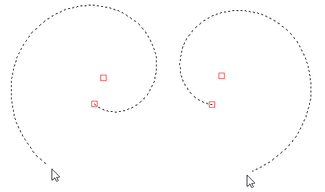
This option allows you to construct a spiral line based on three points. Upon activating this option, you have to specify ![]() three points. First point is the center of the spiral, second point defines the starting radius, third point defines the ending radius. After specifying first and second point, additional option appears in the automenu, allowing you to reverse the spiral direction:
three points. First point is the center of the spiral, second point defines the starting radius, third point defines the ending radius. After specifying first and second point, additional option appears in the automenu, allowing you to reverse the spiral direction:
|
<Tab> |
Change arc direction |
Upon activating this option, select ![]() a graphic line. In result a spline will be instantly created. Shape of the created spline fully coincides with the shape of the selected graphic line.
a graphic line. In result a spline will be instantly created. Shape of the created spline fully coincides with the shape of the selected graphic line.
To finish spline creation, use the following option:
|
<Ctrl>+<Enter> |
Finish Spline input |
Upon finishing the input, the system starts creation of another spline.
To cancel a spline creation, use the following option or the ![]() :
:
|
<Esc> |
Cancel selection |
Whenever two or more control points are defined, the right-click ![]() , as well as the
, as well as the ![]() option, brings up the Right button action dialog, unless the Don't Show this dialog in future option was enabled earlier in the current session. Upon selecting the Continue operation action in the dialog, adding control points to the end of the spline stops, but you can still can add intermediate ones by clicking
option, brings up the Right button action dialog, unless the Don't Show this dialog in future option was enabled earlier in the current session. Upon selecting the Continue operation action in the dialog, adding control points to the end of the spline stops, but you can still can add intermediate ones by clicking ![]() at the desired location on the spline or edit any of the spline's parameters. In order to resume adding points to the end of the spline, select
at the desired location on the spline or edit any of the spline's parameters. In order to resume adding points to the end of the spline, select ![]() the last point in the list of points displayed in the parameters window and click the
the last point in the list of points displayed in the parameters window and click the ![]() Add after button.
Add after button.
Topics in this section:
•Geometrical Parameters of 2D Spline
•General Parameters of 2D Construction Spline
See also: