Geometrical Parameters of 2D Spline |
  
|
Information in this section is applicable both to construction splines and graphic splines.
When creating or editing a spline (except spiral and spline based on graphic line), its geometrical parameters can be edited in the parameters window. Spiral and spline by graphic line do not have user-accessed geometrical parameters.
Spline parameters within the parameters window are split into following tabs:

At the top of the tab there are controls for selecting a type of spline.
Next there is the list of all control points. Each row of the list corresponds to a particular control point. Columns contain following parameters of points:
|
Position of a point on a spline (numbering order). |
|
Coordinates of a point. |
|
If a point was snapped to a 2D node, the node name is shown. |
|
If parameters of derivative at the point were changed for the point, G1 boundary condition will be shown. If radius of curvature at the point was changed for the point, G2 boundary condition will be shown. If a smoothness by other line was applied, a condition corresponding to the applied option will be shown. |
|
If a custom accuracy was applied at the point, this will be indicated by the icon. |
|
If the point was suppressed, this will be indicated by the icon. |
In order to select an already added point, click ![]() either its row in the list, or in the view window. Upon selecting a point its row in the list gets highlighted, its additional parameters get displayed in the parameters window, and its manipulators appear in the view window.
either its row in the list, or in the view window. Upon selecting a point its row in the list gets highlighted, its additional parameters get displayed in the parameters window, and its manipulators appear in the view window.
Following buttons are located to the right of the points list:
![]() Add Before
Add Before
Add a point before the selected one.
![]() Add After
Add After
Add a point after the selected one.
![]() Delete Element from the List
Delete Element from the List
Delete the selected point.
![]() Copy
Copy
Copy coordinates of the selected point to the clipboard.
![]() Paste
Paste
Paste point with previously copied coordinates after the selected one.
![]() Join
Join
Below the list of points there are input boxes, where you can type in X and Y coordinates of a currently selected point. By default, when adding new points, coordinates of a point being defined at the moment dynamically change depending on the cursor movement. However, typing in a coordinate's value using the keyboard enables a checkbox located near coordinate's value input box. Enabling the checkbox fixates the value, so it doesn't depend on the cursor movement anymore. Preview of such point in view window then may only be moved along a horizontal or vertical line corresponding to the typed in value. Such line is indicated by blue dashes. As a click in view window defines coordinates of a point, both coordinates of the current point get fixated, and the system switches to adding another point. Upon selecting an already added point in the list, enabling/disabling coordinates' checkboxes has no effect. In order to re-define coordinates, use the point coordinates manipulator, or re-type values in coordinates' input boxes.
Upon selecting a control point in the list points or in the view window, the Point Parameters tab of the parameters window starts displaying parameters of the selected point. The set of available parameters depends on type of spline.
Following point parameters are available for ![]() Spline and
Spline and ![]() Closed Spline:
Closed Spline:
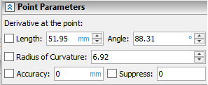
•Derivative at Point
This group of parameters include the Length and Angle of spline's first derivative vector. In other CAD systems similar parameters are sometimes called tangency tension and tangency direction respectively. Angle is measured counterclockwise and zero angle value corresponds to the horizontal right direction of the vector. Upon adding a control point, default values of length and angle are defined automatically. However, you can change values of these parameters by typing in custom values into the corresponding input boxes, or by using manipulators in the view window. Upon changing values of either length, angle or both, the checkbox located to the left of the Length input box gets enabled. Disabling this checkbox reverts length and angle to default values. Moreover, this checkbox get automatically enabled upon changing value of the radius of curvature(see below).
•Radius of Curvature
The spline curvature radius at the selected point. Upon adding a control point, default value of radius is defined. However, you can change value of this parameter by typing in custom value into its input box, or by using the manipulator in the view window. Upon changing a value manually, the checkbox located to the left of Radius of Curvature input box gets enabled. Disabling this checkbox reverts the radius to default value. Moreover, changing the radius of curvature value manually also enables the derivative at point checkbox (see above). Depending on whether the radius of curvature has positive or negative value, the center of curvature is located by one or by other side of the spline.
The Radius of Curvature is measured in the same units as the Length, because the radius of curvature depends on the function of the spline and its derivatives. Therefore, if the units of measurement are changed in the Length input box, then they will also change in Radius of Curvature input box.
•Accuracy
The maximum possible deviation of the spline from the given point. Default accuracy value is zero. Upon typing in a custom value, the checkbox located to the left of the Accuracy input box gets enabled and the specified value gets applied. Disabling this checkbox cancels the application of the custom accuracy, but doesn't restore the default value in the input box. If the accuracy is zero, then the system of linear equations is solved for the spline in relation to the specified control points. If the tolerance is not zero, then the system of inequalities is solved, taking into account the maximum possible given deviation.
The accuracy value is same for all control points. If you change the value for one point, it will be also changed for all other points. However, the application of the specified value is managed separately for each point by enabling/disabling the corresponding checkbox.
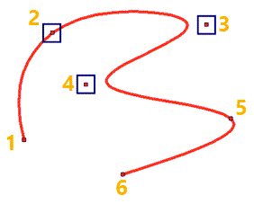
Custom accuracy is applied for points 3 and 4
•Suppress
This option can be used for excluding a particular point from spline curve generation. Suppressed point remains in the list of points and stays displayed in the view window, but the curve no longer passes through it. Enabling the Suppress checkbox excludes a point from curve generation and sets the "1" value in the corresponding input box. Disabling the checkbox includes a point into the curve generation and sets the "0" value in the corresponding input box. Value may also be typed manually or defined by a real variable for controlling the suppression via Parametrization. Any value below "1" is equivalent to zero, so the point isn't suppressed. Any value from "1" and higher is equivalent to "1", so the point is suppressed.
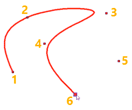
The result of suppressing the point 5
and changing the radius of curvature at the point 2
for the same spline as in the previous picture
Following point parameters are available for ![]() Spline by Polyline and
Spline by Polyline and ![]() Closed Spline by Polyline:
Closed Spline by Polyline:

•Weight
The degree of influence of the point on the spline. By default this value is equal to 1.
•Suppress
See above.
Following point parameters are available for ![]() Polyline and
Polyline and ![]() Closed Polyline:
Closed Polyline:

•Suppress
See above.
Following additional parameters are available for splines of any type, except Polyline and Closed Polyline:
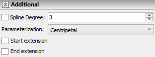
•Spline Degree
This parameter may only be edited outside the mode of control points adding. Defines the degree of polynomials that describe the spline. When creating a spline, its degree increases automatically up to the third, according to the number of the points added. By default all the splines are built as cubic ones.
•Parameterization
It determines the mathematical method of spline description. There are the following variants available: By length, Centripetal, Uniform, Local sums, Fixed. The detailed information on this parameter is available in the Main Concepts of 2D Spline section.
There are additional checkboxes available for open splines only: Start extension and End extension. Upon enabling these checkboxes, similar set of extension parameters appear below each checkbox:
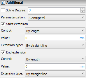
•Control
Extension Value input method:
oBy length
Extension value is measured in absolute length units.
oBy Parameter
Extension value is measured in portions of the spline's initial length.
•Value
Length of section that is added (if positive value) or removed (if negative value) at the starting or ending point of the spline.
•Extension type
The mathematical method of extension interval description (shape of section that is added to the start or end of the spline): By straight line, Keep curvature, Mirror, By parameter, By arc. The detailed information on this parameter is available in the Main Concepts of 2D Spline section.
See also:
•General Parameters of 2D Construction Spline