Main Concepts of 2D Spline |
  
|
Information in this section is applicable both to construction splines and graphic splines.
This section contains mathematical description of spline parameters, such as:
•smoothness (tangency) at points snapped to graphic lines.
The parameterization significantly affects the shape of the spline, especially in areas with closely spaced points that change the direction of the curve.
When changing the type of parameterization, the same parameter values may correspond to a different configuration of the spline. There will be a different length of the arc between two control points of a spline.
The following methods of spline parameterization are available:
•Fixed;
•Uniform;
By default the Centripetal parameterization is used for splines.
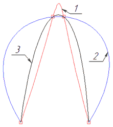
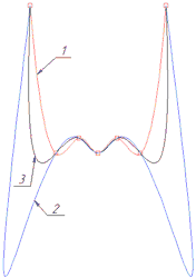
1 - Uniform, 2 - By length, 3 - Centripetal
When changing positions of control points or adding points, the parameterization of the spline is recalculated. This is necessary when creating or editing a new spline, therefore, for the spline being built or being edited, the fixed parameterization is not available. If the spline was split, trimmed or imported from another system, then it will have a fixed parameterization. In the fixed parameterization mode, spline editing is limited. This is due to the fact, that the length of the arc changes upon editing, but the parameters' values are fixed. When distance between points increases, flat areas can be formed, and when it decreases, loops are formed.
When trimming or splitting a spline, its parameterization type automatically becomes fixed. The type of parameterization for a fixed spline can be changed, but then its geometry will change. In the fixed parameterization mode, it is permissible to make only minor adjustments to the spline.
If the split/trimmed spline have only three or two control points, then changing the parameterization from fixed to any other is not recommended. By default, splines are built on the basis of cubic polynomials, and three points for the correct construction of a cubic spline are not enough. So you should either lower the degree of the spline, or do not change the type of parameterization.
If the spline was split or trimmed, then to save the geometry, the first and second derivatives are fixed at the two extreme points of the spline. If spline editing is necessary, it is recommended to remove the fixation of derivatives by disabling checkboxes in points' parameters.
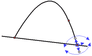
Parameters are distributed in accordance with the length of the arcs between adjacent points. Such arcs are curves constructed on polynomials, i.e. the spline can be represented as a sequence of arcs.
Let's say, we have spline with Dk control points, where k = 0, 1, ..., n.
The length of all arcs (spline length) L will be defined by the expression:

Arc length Lk from D0 to Dk:

The definition domain of the parameters is t [0,1].
Each tk parameter should match the length Lk, then:
t0=0
|
where k= 0, 1, …, n-1 |
t1=1
The arc length parameterization method is widespread and usually works well. You should take into account, that the polynomial spline between two points is not an actual arc — it can be considered an arc only approximately. If the arc is long, a spline constructed using this type of parameterization can have a great convex.
The name of the method reflects its physical interpretation. When moving along a spline trajectory, the stronger the bend, the greater the centripetal force. The centripetal force is proportional to the angle change. The centripetal parameterization method is an approximation to such a physical model. From the mathematical point of view, the centripetal method of parameterization is a modification of the method of parameterization by length.
Let's say, we have spline with Dk control points, where k = 0, 1, ..., n.
The definition domain of the parameters is t [0,1]. We introduce the exponent α, which will modify the expressions of the method of parameterization by length:

t0=0
|
where k= 0, 1, …, n-1 |
t1=1
If α = 1, then the centripetal parameterization and parameterization along the length result in the same geometrical shape.
If α ˂ 1, ![]() and
and ![]() , then the influence of a longer arc decreases. Influence means the value of the parameter change for the corresponding arc.
, then the influence of a longer arc decreases. Influence means the value of the parameter change for the corresponding arc.
If α < 1, ![]() and
and ![]() , then the influence of a short arc increases.
, then the influence of a short arc increases.
Uniform
Let's say, we have spline with Dk control points, where k = 0, 1, ..., n.
The definition domain of the parameters is t [0,1].
The extreme parameters are t0 = 0 and t1 = 1.
Other parameters are 1/n, 2/n, ..., (n-1)/n.
With uniform parameterization sharp protuberances, peaks, loops are possible more often than in other methods. At the same time, this type of parameterization is the most simple and intuitive.
This parameterization method is available for compatibility of splines built in T-FLEX CAD 15 and earlier. When creating splines in later versions of the T-FLEX CAD it is better to use By length, Centripetal and Uniform methods.
Extension allows you to increase (if value is positive), or decrease (if value is negative) a length of a spline by adding or removing segments at its extreme points. Length can be increased, using various mathematical laws, resulting in different shapes. A law of extension is defined by the Extension type parameter. If extension value is negative, then the extension type does not affect the geometry of the spline.
The following extension types are available.
•By straight line
With this method, only the first derivative is a smooth function. A tangent straight line segment is added at the starting or ending point of the the spline. Curvature continuity is not preserved
•Keep curvature
Both the first and second derivatives are smooth functions. This automatically sets a smooth decrease in curvature to zero. I.e., the added segment starts with the same curvature as the adjacent segment of the spline and then smoothly becomes straight in such way that the curvature continuity is preserved.
•Mirror
The added segment is symmetrical to the spline about the line perpendicular to the tangent built at the starting or ending point of the spline.
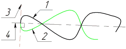
Mirror extension: 1 - source spline; 2 - added segment; 3 - tangent at the starting point; 4 - perpendicular to the tangent
•By parameter
The curvature continuity is preserved; a smooth decrease of the curvature occurs throughout the entire offset section. At the end of the added segment the curvature reaches zero and the radius of curvature reaches infinity.
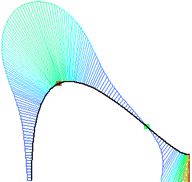
Curvature diagram for extension by parameter demonstrates the smooth decrease of curvature without breaks.
•By arc
Only the first derivative is a smooth function, the curvature continuity is not preserved. A tangent circular arc is constructed from the starting or ending point of the spline. Radius of the arc is equal to the radius of curvature at the said point.
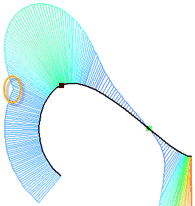
Curvature diagram for extension by arc has the break.
Smoothness (tangency) at points snapped to graphic lines
If a control point of a spline is snapped to a graphic line, then you can specify one of three options for the smoothness of the spline at such point. Upon selecting the point, following smoothness options are available in the automenu and dynamic toolbar:
•G1 - first derivative (tangency) continuity
Directions of tangents to spline and to snapping curve coincide in the selected point. This means, that angles of the first derivative of both lines at the extreme points will either be equal or differ by a multiple of 180°. For example, let's draw two consecutive splines: the last point of the first spline coincides with the first point of the second. For the second spline we apply the G1 smoothness at the starting point. Angles of the tangent at the ending point of the first spline and at the starting point of the second one are equal.
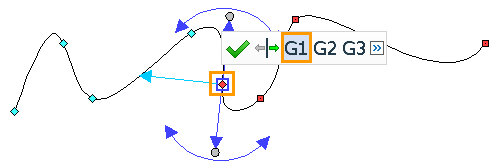
When using the G1 smoothness, other parameters of two lines at the selected point might be different.
The use of G1 smoothness is possible only for splines of the second degree and higher.
•G2 - second derivative (curvature) continuity
Directions of tangents and centers of curvature coincide for spline and snapping curve in the selected point. I.e.: the equality of the radii of curvature is added to the G1 condition. For example, let's draw an arc with a radius of 35 mm continued by a spline. We apply the G2 smoothness at the starting point of the spline. The radius of curvature at the starting point of the spline is equal to 35 mm. Moreover, drawing a tangent at the ending point of the arc demonstrates, that its direction coincide with the direction of the tangent to the spline, since the angle of the constructed tangent is equal to the angle of the first derivative at the starting point of the spline.
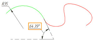 The sign of the radius of curvature defines the direction of twisting of the spline. If the spline and the snapping curve have different twisting directions, then, upon applying the G1 smoothness, point of sign change (inflection point in the case of continuity) of the curvature function is at the starting point of the spline. Upon applying the G2 smoothness, the inflection point will shift inside the spline, and a bend will be added to the spline itself with the same direction of twist as the snapping curve. This is necessary to satisfy the condition of coincidence of centers of curvature of the lines at the selected point. For example, lets take a look at two consecutive splines. The last segment of the first spline is twisted clockwise, the first segment of the second is twisted in the opposite direction. Let's display the curvature diagram for these splines using the |
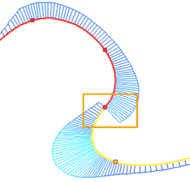
It can be seen on the diagram, that the curvature function changes sign at the last point of the first spline and the first point of the second spline, and in this case with the function breaking.
Let's apply the G2 smoothness to the last point of the first spline. It can be seen on the diagram, that the inflection point has shifted into the first spline: a small section was added to the first spline with a twisting direction corresponding to the direction of the second spline.
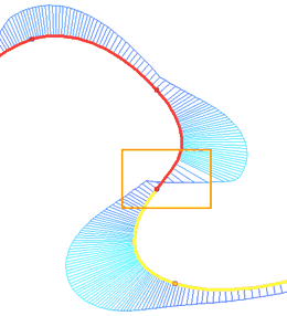
It should be noted, that the curvature function became continuous, but at the extreme points the smoothness of the curvature function is broken. To maintain the smoothness of the curvature function at the extreme points of the spline, there is a third version of smoothness.
The use of G2 smoothness is possible only for splines of the third degree and higher.
•G3 - third derivative continuity
Directions of tangents to lines, curvature centers and directions of tangents to curvature functions coincide for spline and snapping curve in the selected point. I.e.: the smoothness of the curvature function is added to G1 and G2 conditions. Let's continue studying the previous example with two consecutive splines. This time we apply the G3 smoothness instead of the G2 smoothness for the extreme point of the first spline. It can be seen on the diagram, that, when using G3 smoothness, the curvature function preserves smoothness at the extreme points of the splines.
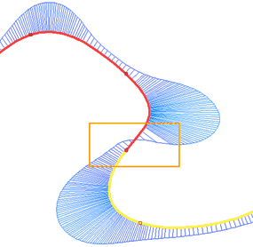
The use of G3 smoothness is possible only for splines of the fourth degree and higher. If the spline has a degree below fourth, then applying the G3 smoothness automatically increases the degree of the spline to the fourth.
If we compare the G1, G2, and G3 smoothness by their influence on the curvature function, we'll see the following rule:
G1 - the curvature function does not preserve continuity at the selected point;
G2 - the curvature function is continuous, but does not preserve smoothness at the selected point;
G3 - the curvature function is continuous and retains smoothness at the selected point.
|
|
|
G1 |
G2 |
G3 |
See also: