3D Model Elements on 2D Projection |
  
|
The Elements tab of the ![]() 2D Projection command allows you to select, which elements of the 3D model will be displayed on projection.
2D Projection command allows you to select, which elements of the 3D model will be displayed on projection.

By default, for Bodies and operations the mode All Elements is set, whereas for profiles, paths and coordinate systems – mode Selected Elements. For geometric elements (faces, edges, loops) the method of projection is not specified (only selected elements are always projected).
You need to select elements in cases where you need to project not the entire model, but only individual elements (specific operations, Solids or construction elements / topological elements) or if the projection will be used to create 3D elements. In addition, there are often cases when some objects of the model simply cannot be seen on the projection due to the fact that they are covered by other bodies. For example, some parts may be inside the case. In this case, it is useful to exclude from the projection those objects that are still not visible. This will save time when recalculating such a projection.
In order to select individual elements of the model, you must use the option that is available in each projection mode:
|
<E> |
Select model elements to project |
This option has a drop-down list of filters to select the desired objects. You can select Bodies, Operations, Welds, 3D Profiles, 3D Paths, Coordinate Systems, 3D Axes, Cable Products and Geometric Elements. You may use filters, when selecting objects.

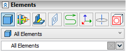
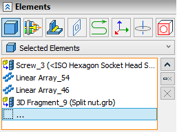
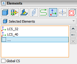
When the ![]() option is activated, the Elements section automatically opens in the parameters window. This section contains a list in which selectable items are entered. The list is divided into separate tabs according to the type of selected objects.
option is activated, the Elements section automatically opens in the parameters window. This section contains a list in which selectable items are entered. The list is divided into separate tabs according to the type of selected objects.
|
Bodies and operation |
|
Welds |
|
3D Profiles |
|
3D Paths |
|
Coordinate System |
|
3D Axes |
|
Cable Components |
|
Geometric Elements |
You can also activate the selection mode of projected elements using the parameters window. It is enough to place the cursor in a free line of the list marked with an ellipsis, and the option ![]() is turned on automatically.
is turned on automatically.

For each type of selected elements, you can specify the projection method:
•All Elements - all elements of this type in the scene will be projected;
•Selected Elements - only selected elements of this type will be projected;
•All Excluding Selected - all elements of this type will be projected, except for the selected ones;
•From File (only for Bodies and Operations) - this option is set if the projected operations and Bodies are selected from an external file (see the section 2D Projection by External Model). When this item is selected in the command automenu, the file selection option ![]() is automatically enabled ;
is automatically enabled ;
•As in Operation (only for welds) - the method of projecting welds will depend on the method set for the operation and Bodies. If the operations are set to All Elements, then all welds are projected. If any other method is set for operations, the welds are not projected.
Coordinate system projection has a number of features. Coordinate systems are projected over the entire 3D model without regard to visibility. Coordinate system projection lines are not considered when defining projection boundaries.

Projections of the coordinate system are formed from three graphic lines with arrows. The color of each line-axis coincides with the color of the corresponding axis of the global coordinate system in the 3D scene. The style of the lines can be modified as for the standard graphic lines of the drawing.
The length of the coordinate system axes is controlled by the parameter View > Size > LCS in the dialog of the command Set Document Parameters, 3D tab.
Projecting of the global coordinate system is enabled separately by enabling the Global CS checkbox. Selected method for projection of LCS does not affect projection of global coordinate system.
The automenu provides a separate option for quick selection of all operations currently present in the 3D scene:
|
<A> |
Select all Solids in current scene |
The difference between the behaviors of the option Select all Solids in current scene and that of the mode of projecting the whole scene can be described as follows. The list of all operations selected in the 3D scene is formed at the time of using the option and stays unchanged unless intentionally modified. Therefore, the new bodies added to the scene do not appear in the list of the elements to be projected.
See Also:
•2D Projection by External Model