Local Section View > Application |
  
|
The Application mode of the Local Section View command can be used for creating a local section view as a separate projection, which overlaps another existing projection. Upon calling the command, this mode can be enabled using the button located in the parameters window.
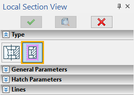
In order to create a local section view in this mode, perform following actions:
1.Define section view's contour.
2.Define position of cutting plane.
3.Specify elements for the section to be applied to (optional step).
4.Set hatch parameters (optional step).
5.Specify elements to be taken into account, when projecting (optional step).
6.Set parameters of lines (optional step).
7.Finish input by pressing ![]() button in the automenu or in the header of the parameters window, or by pressing <Ctrl>+<Enter> on keyboard.
button in the automenu or in the header of the parameters window, or by pressing <Ctrl>+<Enter> on keyboard.
Upon creating a local section view, it appears in the 3D model tree as a separate projection.
In order to create a local section view, first you have to define a shape of view's contour. There are two ways of doing it: selecting an existing hatch and creating a new hatch by a new spline.
In order to select an existing hatch, use the following automenu option:
|
<1> |
Select Hatch as boundary of local section view |
This option is active by default, upon calling the command. In result, pressing ![]() within drawing window selects a nearest of the hatches belonging to 2D projections. The local section view will be created on a 2D projection, which the selected hatch belongs to.
within drawing window selects a nearest of the hatches belonging to 2D projections. The local section view will be created on a 2D projection, which the selected hatch belongs to.
In order to re-select a hatch, re-activate the option.
Upon completing creation of the local section, the hatch becomes invisible, while overlapping a portion of the main projection. The lines of the local section will be drawn with higher priority, than those of the hatch and the main projection.
In order to create a new hatch by a new spline, use the following automenu option:
|
<6> |
Create Hatch by Spline |
Upon activating this option, click ![]() on a drawing sheet. In result the spline creation command will be launched. The spline, and therefore the local section view, will be created on a projection nearest to the point of clicking. Unlike the local section view within projection, the application mode doesn't let you see the hidden lines of the projection, when constructing the spline, but you can use object snappings.
on a drawing sheet. In result the spline creation command will be launched. The spline, and therefore the local section view, will be created on a projection nearest to the point of clicking. Unlike the local section view within projection, the application mode doesn't let you see the hidden lines of the projection, when constructing the spline, but you can use object snappings.
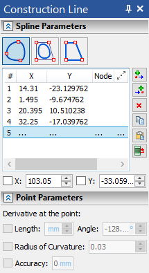
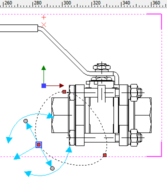
Upon finishing spline creation, the system returns to local section view command, automatically creates an invisible hatch by the resulting spline, and selects this hatch as a section view's contour.
After creating a spline, it can be edited. To do so activate the spline creation option again. In result, the standard spline editing command will be launched. As you finish the spline editing, the system will automatically return to the local section view creation command.
If the creation of a spline was done by mistake, you can undo it using the following automenu option:
|
<G> |
Reset Created Hatch |
Name and icon of the 2D projection the hatch belongs to, are displayed in the Projection box of the parameters window. In order to change the projection, select or create a different hatch. the contour of the selected hatch is indicated by blue lines in drawing window.
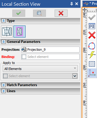
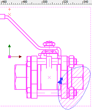
Upon defining a contour, you should select a point defining cutting plane's position. To do so, activate the following automenu option:
|
<3> |
Select point that defines cutting plane position |
Upon activating this option, filters for selecting ![]() points become active on the filter toolbar. You can select either a 3D point in 3D window or 2D point belonging to another projection in drawing window. Selecting a 2D point other than node results in automatic creation of a 2D node at the selected point.
points become active on the filter toolbar. You can select either a 3D point in 3D window or 2D point belonging to another projection in drawing window. Selecting a 2D point other than node results in automatic creation of a 2D node at the selected point.
Cutting plane parallel to parent projection's plane passes through the selected point. Name and icon of the selected point or its parent elements are displayed in the Binding box of the parameters window. You can ![]() Clear the selection, if necessary, using button located at the right side of the box. In order to re-select a point, activate the aforementioned option again. The option may also be activated by clicking the Binding box.
Clear the selection, if necessary, using button located at the right side of the box. In order to re-select a point, activate the aforementioned option again. The option may also be activated by clicking the Binding box.
Applying local section to 3D model elements
After creating a contour, you can specify, which elements of 3D model should be cut in the local section view. It can be done, using the Apply to group of controls located in the parameters window at the bottom of the General Parameters tab.
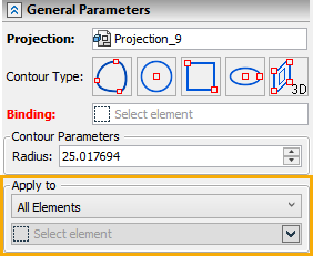
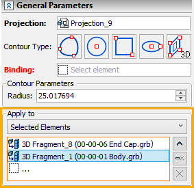
One of the following methods of applying section can be selected in the drop-down list:
•to All Elements,
•to Selected Elements,
•to All Excluding Selected.
The list of elements for Selected Elements and All Excluding Selected methods is located below.
By default, section is applied to All Elements. The elements list is empty and inactive, when using this method
Upon selecting a method, which presumes elements selection, filters for selecting bodies, welds and cable components become active on the filter toolbar, so you can select desired elements by clicking ![]() them in 3D scene or in model tree. Names and icons of selected elements are displayed in the list. Elements can be selected in the list using
them in 3D scene or in model tree. Names and icons of selected elements are displayed in the list. Elements can be selected in the list using ![]() . The list can be managed using Expand
. The list can be managed using Expand ![]() , Collapse
, Collapse ![]() , Delete Element from the List
, Delete Element from the List ![]() and Clear
and Clear ![]() buttons located to the right. .
buttons located to the right. .
It is possible to specify beforehand that a 3D fragment will NOT be cut by a section, when creating a section view of an assembly, if some conditions are met. These conditions can be set in 3D fragment's document parameters (Document Parameters > Document > 3D Fragment > Sections) and is usually used in the libraries of standard parts.
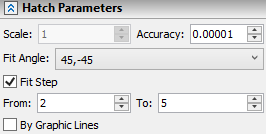
Upon creating a new local section, it is assigned default hatch parameters. You can edit Hatch Parameters in the eponymous tab of the command's parameters window, if necessary. The detailed information on hatch parameters can be found in the Parameters of Sections on 2D Projection section. Unlike local sections within projections, hatch parameters of an application section are not linked to parameters of a parent projection.
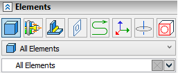
In the Elements tab you can specify, which of the model elements should be taken into account, when projecting. The content of this tab of the Local Section View command's parameters window is the same as of the eponymous tab of the 2D Projection command's parameters window (see the 3D Model Elements on 2D Projection section).
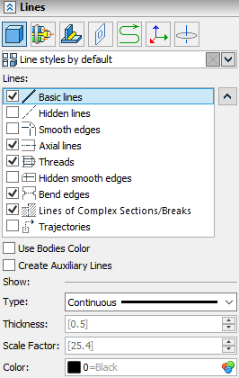
Parameters of lines representing elements of different types can be customized for a local section view in the Application mode, using the Lines tab of the parameters window in the same way, as it is done for 2D projections of other types. By default, a local section view inherits lines parameters of its parent projection. However, you can edit them independently of parameters of the parent projection.
Local Section View in 3D Model Tree
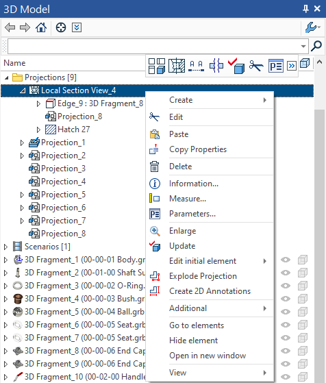
Local section views created in the application mode are displayed in the 3D Model Tree as separate projections of a special type. The lower (in relation to local sections) level of the tree contains points defining cutting plane and/or elements, which these points belong to; hatches defining section contour and their parent objects; and parent projections.
Contextual menu of local section views in the tree is the same as of other projections. The ![]() Edit command of the contextual menu invokes the Local Section View command for editing the selected view. Editing is performed in the way similar to creating a new local section view.
Edit command of the contextual menu invokes the Local Section View command for editing the selected view. Editing is performed in the way similar to creating a new local section view.
Parameters Dialog of Local Section View
During creation and editing of a local section view its parameters dialog can be invoked using the following automenu option:
|
<P> |
Set entity Parameters |
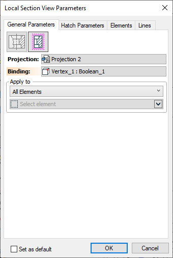
The dialog contains following tabs:
•General Parameters;
•Hatch Parameters;
•Elements;
•Lines.
The content of the dialog's tabs is the same as the content of the eponymous tabs of the parameters window of the Local Section View command.
The Set as default checkbox is displayed at the bottom of the dialog, regardless of the active tab. Enabling it sets values specified in the Hatch Parameters and Lines tabs as defaults for all 2D projections and local section views created further (except the fact that default lines parameters of local section views created in the application mode are inherited from parent projections).
After creating a local section view, its parameters dialog can also be invoked from the contextual menu or by double-clicking ![]()
![]() the view in the 3D model tree. The dialog invoked this ways contains wider set of parameters similar to the parameters dialog of projections of other types.
the view in the 3D model tree. The dialog invoked this ways contains wider set of parameters similar to the parameters dialog of projections of other types.
See Also:
•Local Section View > Within Projection