Arrow View |
  
|
The command can be called in one of the following ways:
Icon |
Ribbon |
|---|---|
|
Assembly (3D) > Additional > Arrow View Weld > Additional > Arrow View |
Keyboard |
Textual Menu |
<3АJ> |
|
It is also available as option in the 2D Projection command:
|
<3> |
Create arrow view |
Before creating an Arrow View it is necessary to add to the drawing an arrow defining a direction of an arrow view.
Activate a view, from which the projection will be taken, call the Section command and select the following option:
|
<3> |
Arrow View |
Now you can put an arrow on the drawing, it is possible to snap to any objects in the model or to place it at any place. By default, the arrow is directed to the right, for more precise direction setting, you can use the automenu options:
|
<N> |
Select node |
|
<B> |
Select first attachment point |
|
<E> |
Select second attachment point |
|
<Z> |
Changing view direction |
|
<H> |
Changing text placement |
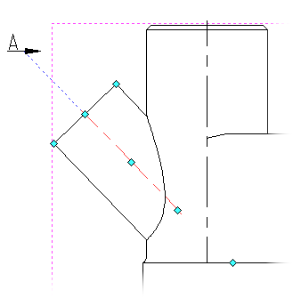
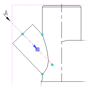
With the help of the option ![]() , you can select the first attachment node to the projection, for convenience, the system automatically extends the lines, for more convenient placement of the arrow:
, you can select the first attachment node to the projection, for convenience, the system automatically extends the lines, for more convenient placement of the arrow:

Then the system automatically prompts you to select the second attachment node.

Additionally, you can use the options ![]() and
and ![]() . The option
. The option ![]() is used to change the position of the arrow rotates the arrow clockwise by 90 degrees with each activation, and the option
is used to change the position of the arrow rotates the arrow clockwise by 90 degrees with each activation, and the option ![]() is used to change the position of the text moves the text in two possible positions - above the arrow or below the arrow.
is used to change the position of the text moves the text in two possible positions - above the arrow or below the arrow.
After the arrow has been created, you can start forming the projection.
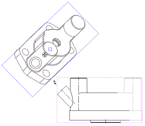
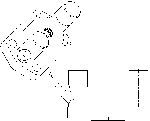
To do this, call the Arrow View command and then select the newly built arrow in the drawing.

An additional one will be built relative to the main view. By default, the secondary view maintains a projection relationship with the main view. In order to break the connection with the view, you must deactivate the option in the automenu:
|
<K> |
Set / Break link with projection |
Last steps - position the projection in the drawing and, if necessary, select the elements of the model for projection.

See Also:
•Algorithm of Creating 2D Projection
•General Parameters of 2D Projection
•Position of 2D Projection on Drawing
•Additional Parameters of 2D Projection
•3D Model Elements on 2D Projection
•2D Projection by External Model
•Parameters of Sections on 2D Projection