Cutting Line, View Arrow, View Label |
  
|
The command can be called in one of the following ways:
Icon |
Ribbon |
|---|---|
|
Draw > Appearance > Section Sheet Metal (2D) > Appearance > Section Workplane > Appearance > Section |
Keyboard |
Textual Menu |
<SE> |
Draw > Section |
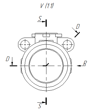
This command creates cutting lines, view arrows and view labels. Cutting lines and view arrows placed on 2D projections of 3D model can be used for creating projections of a corresponding type (see Section Cut and Section View, Arrow View).

Upon calling the command, you need to activate one of the following automenu options, in order to select a type of an element to be created:
|
<S> |
|
|
<D> |
|
|
<R> |
|
|
<V> |
The two point section option is active by default.
Callouts and labels of circular detail views are created automatically, when you create a view using the Detail View with Caption command.
Callouts of arbitrary-shaped detail view can be drawn manually, using graphic lines
Upon selecting a type of element to be created, its preview starts following the cursor. Then you have to define anchor points using one of the methods described in the Snapping of Cutting Lines, View Arrows and View Labels section. Number of anchor points depends on the type of element and its desired configuration. Upon defining all necessary points, the system switches to creation of a next element.
At any stage of creating an element you can customize its parameters using either the ![]() parameters tool window, which is displayed automatically, or the
parameters tool window, which is displayed automatically, or the ![]() parameters dialog, which can be invoked by activating the following automenu option:
parameters dialog, which can be invoked by activating the following automenu option:
|
<P> |
Set Section Line Parameters |
In addition to options described above, the automenu of the Section command contains options specific for particular type of element. Such options are described in sections describing corresponding element types. Moreover, there's the option of selecting a 2D node. It is described in the Snapping section. And finally, there are following options, which are common for most 2D elements creation commands:
|
<Ctrl>+<Enter> |
Finish input |
|
<Alt>+<P> |
|
|
<F4> |
|
|
<Esc> |
Exit command |
Topics in this section:
•Snapping Cutting Lines, View Arrows and View Labels
•Switching Camera between View and View Designation
•Edit Cutting Line, View Arrow or View Label
See Also:
•Font Parameters of Drawing Detailing Elements
•Change Size of Font and Arrows for All Elements on Current Page