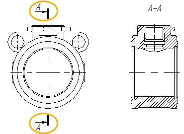
Cutting Line |
  
|

A cutting line of two-point section can be created using the following automenu option of the Section command:
|
<S> |
Create two point Section |
This option is active by default, upon calling the command.
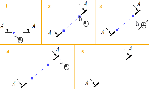
After activating the option, you have to define three points, using one of the methods described in the Snapping section. First and second points define the position of the cutting line, the third one defines offset from two others to the arrows of the cutting line. One of the arrows is located at the intersection of the cutting line and a normal to the cutting line from the third point; another arrow is located symmetrically to the first one. Positions of arrows represent the actual endpoints of the cutting line. Fist and second points are indicated by square blue markers connected by the thin dashed line.

After defining the third point, the creation of the current cutting line ends, and the system starts creation of another one.
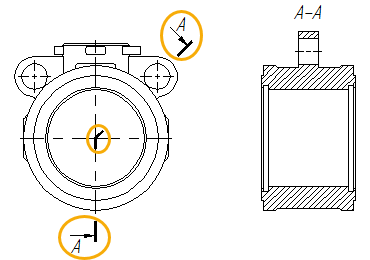
The view direction in relation to the cutting line can be switched to opposite, using the following automenu option:
|
<Z> |
Change View Direction |

The cutting line of multiple-point section can be created using the following automenu option of the Section command:
|
<D> |
Create multiple point section |
This option works in the same way as the single point section. The only difference is that for multiple-point section you can define unlimited number of anchor points. Points are defined, using one of the methods described in the Snapping section. Upon defining one point, the command starts defining of another one, and so on. After defining the desired number of points, you need to confirm the input, using the following option:
|
<Ctrl>+<Enter>, <End> |
Finish input |
The cutting line is constructed as a polyline connecting points in the order of their creation.
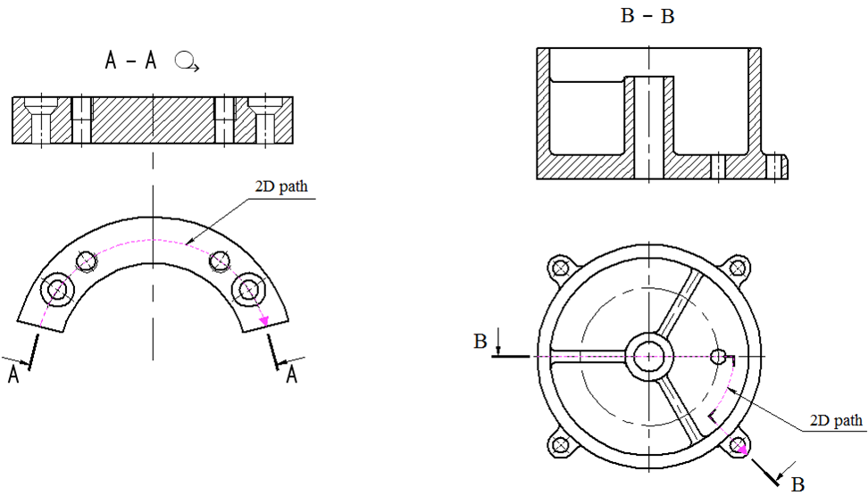
Instead of defining particular points, you can use an existing 2D path as a cutting line. Path can be selected using the following option:
|
<T> |
Select 2D path |

Next, you have to set offset from endpoints of the cutting line to the arrows. It is done by defining another point in the same way, as described for the one-point section.
After defining the last point, the creation of the current cutting line ends, and the system starts creation of another one.
The view direction in relation to the cutting line can be switched to opposite, using the following automenu option:
|
<Z> |
Change View Direction |
Using a cutting line for creating a section cut or section view
If a 2D projection or drawing view is active at the moment of creating a cutting line, the line belongs to such projection/view. If no projections/views are active, but the first anchor point of the cutting line lays within projection's boundaries, then such line also belongs to the projection. Cutting lines belonging to 2D projections of 3D models can be used for creating section views and section cuts, using the Section View command.
Topics in this section: