Parameters of Cutting Line |
  
|
Parameters of a view label can be customized either in the ![]() Parameters tool window or in the
Parameters tool window or in the ![]() Parameters dialog
Parameters dialog
Following tabs are displayed in the parameters window, during creation of a cutting line:
•General;
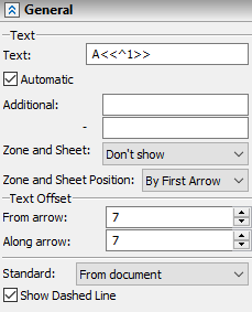
The tab contains following parameters:
Text group:
•Text
Main text (view name), which is displayed at the outer sides of cutting line's the arrow.
•Auto
This checkbox is enabled by default, upon calling the command. As a result, the first letter in the alphabet, which is not used by other views, gets assigned as a cutting line's text. If all letters are used, then a subscript index number gets added to the letter (A1, B1, ... Z1, A2, B2 and so on). In future, upon deleting a view, names of all views, that are below the name of the deleted one in alphabetical order, will be automatically reassigned, in order to ensure the continuous numbering. If you disable this checkbox upon creating or editing a cutting line, its text will remain the same independently of names of other views.
•Additional
This parameter have two input boxes, where you can type in additional texts for each arrow. The additional text is displayed near the main text in the same line.
•Zone and Page Display
A number of a zone and/or number of a page, where a linked view label is located, can be added to the text of a cutting line. The drop-down list contains following options of number display: No, Zone, Page, Page and Zone, Page or Zone. The result of applying the Page or Zone option depends on document parameters for the page of linked view label (Document Parameters > Page > Paper > Zones > Zones). If the Detect Zones for Bills of Materials parameter there has the No value, then a number of sheet is displayed, otherwise - number of zone.
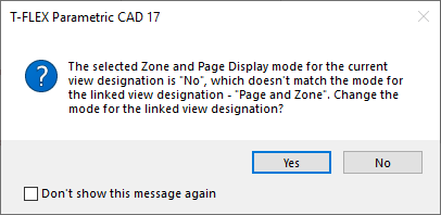
The Zone and Page Display parameter takes effect, only after creating a linked view label. When creating a linked view label (manually or by using the cutting line for generating a section view/cut), then the label automatically gets the same Zone and Page Display option as the cutting line. In such case, manual change of the option for the cutting line invokes a dialog, where the system asks, if the same option should be applied to the linked label, and vice versa.
The detailed information on zones and their customization is available in the Zones. Document Parameters section.
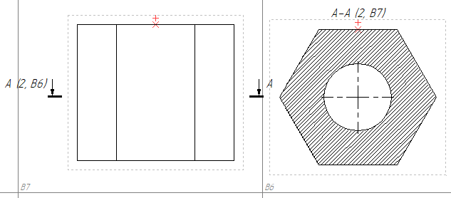
•Zone and Page Position
A number of a zone/page can be displayed By First Arrow or By Second Arrow.
Text Offset group:
•From arrow
Distance between arrow and nearest symbol of the text measured normal to arrow.
•Along arrow
Distance between cutting line and center of text measured along arrow.
Standard
The section line can be drawn in accordance with either DIN/ISO or ANSI standards. The difference is shown below. If the value of this parameters is set to From document, then the applied standard depends on document parameters (Document Parameters > Page > Dimensions > Dimensions > Standard).
|
|
DIN/ISO |
ANSI |
Show Dashed Line
This checkbox affects only the ANSI standard cutting lines. The effect is shown below.

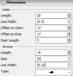
The tab contains following parameters:
Lines group:
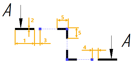
1 - Length.
2 - Line Width. If a value is displayed in the square brackets, then it is defined by document parameters (Document Parameters > Page > Lines > Lines > Thick Lines).
3 - Offset on Start.
4 - Offset on End.
5 - Dash Length. For DIN/ISO lines defines length of dashes at line jogs. For ANSI lines defines length of all dashes except starting and ending ones.
Arrows group:
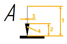
1 - Length.
2 - Size. If a value is displayed in the square brackets, then it is defined by document parameters (Document Parameters > Page > Lines > Line Style > Arrow (End) Size).
3 - Line Width. If a value is displayed in the square brackets, then it is defined by document parameters (Document Parameters > Page > Lines > Lines > Other Lines).
4 - Type. Type of the arrow tip can be selected in the drop-down list.
The parameters dialog of a cutting line can be invoked in one of the following ways:
•double clicking ![]()
![]() a cutting line in a view window or in the
a cutting line in a view window or in the ![]() Model Elements window;
Model Elements window;
•from the contextual menu, that appears upon clicking ![]() a cutting line in a view window or in the
a cutting line in a view window or in the ![]() Model Elements window;
Model Elements window;
•from the dynamic toolbar, that appears upon selecting a cutting line in a view window;
•from the automenu of the Section View and Edit Section commands.
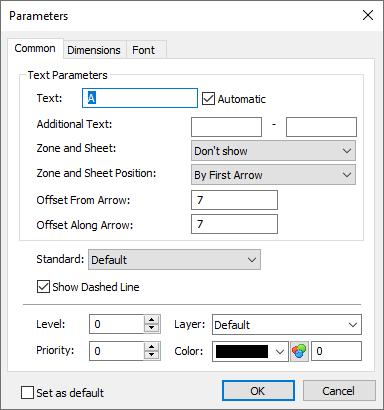
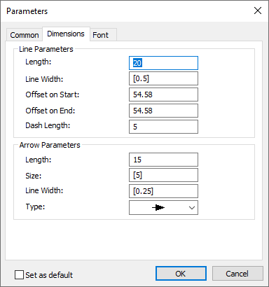
The parameters dialog of a cutting line label contains following tabs:
•Common
This tab contains same parameters, as the General tab of the parameters tool window described above. Additionally, Level, Priority, Layer and Color can be customized in the bottom of the tab.
•Dimensions
This tab contains same parameters, as the eponymous tab of the parameters tool window described above
•Font
This tab contains the same parameters, as the similar tab in parameters dialogs of other detailing elements.
See Also: