Snapping Cutting Lines, View Arrows and View Labels |
  
|
Upon selecting a type of element to be create, the preview starts following the cursor. Next, you have to define anchor points. Number of points depends on the type of element and its desired configuration., but methods of defining points are the same anyway. There are following methods of defining anchor points:
•Move the mouse cursor over an arbitrary location in the drawing and click ![]() or press <Enter>.
or press <Enter>.
The point will be snapped to the position of the cursor in the moment of clicking/pressing. Then the system will switch either to defining a next point or to creating a next element. When pointing a location you can use object snapping and snap anchor points to:
o2D nodes;
ostarting, middle and ending points of graphic lines;
ointersections of construction lines (when selecting an intersection, a 2D node is created there automatically).
When snapping anchor points to such elements, an associative link gets created between the resulting and selected elements, i.e. the position of resulting element will change in future upon changes in position of selected element.
•Type in the X and Y Coordinates in the parameters window.
![]()
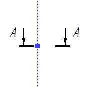
Initially, the Coordinates tab of the parameters window displays coordinates of the mouse cursor. If a drawing view or 2D projection of 3D model is active, the coordinates are measured in its coordinate system; otherwise - in current page's coordinates system. If you move the cursor over one of the coordinates input boxes and click ![]() , you can type in values using the keyboard. Upon typing in a value, the checkbox located to the left of the coordinate input box gets enabled automatically. In result, the preview gets fixed along the corresponding axis. So, the preview then can be moved only along a particular vertical or horizontal line. Such line is indicated by blue dashes.
, you can type in values using the keyboard. Upon typing in a value, the checkbox located to the left of the coordinate input box gets enabled automatically. In result, the preview gets fixed along the corresponding axis. So, the preview then can be moved only along a particular vertical or horizontal line. Such line is indicated by blue dashes.

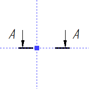
Next, you can either type in the second coordinate in the same manner, or place the preview in desired location by moving the mouse cursor and click ![]() or press <Enter>. If the second coordinate is defined by moving the mouse, then the system automatically switches to defining a next anchor point or to creating a next element. If the second coordinate is typed in from the keyboard, the preview gets fixed along both axes, which is indicated by the second dashed blue line.
or press <Enter>. If the second coordinate is defined by moving the mouse, then the system automatically switches to defining a next anchor point or to creating a next element. If the second coordinate is typed in from the keyboard, the preview gets fixed along both axes, which is indicated by the second dashed blue line.

Finally, you have to confirm the coordinates by clicking ![]() or pressing <Enter> anywhere in the drawing. In result, the system will move on to defining a next anchor point or to creating a next element.
or pressing <Enter> anywhere in the drawing. In result, the system will move on to defining a next anchor point or to creating a next element.
•Activate the following automenu option:
|
<N> |
Select Attachment Node |
Upon activating this option, a click ![]() in the drawing window snaps the current anchor point to a nearest existing 2D node. In this case, an associative link gets created between the created object and the selected 2D node, same as if you select a node using object snapping.
in the drawing window snaps the current anchor point to a nearest existing 2D node. In this case, an associative link gets created between the created object and the selected 2D node, same as if you select a node using object snapping.
Upon defining all necessary points, the system automatically switches to creation of a next object.