Create Detail View with Caption |
  
|
The detail view with caption creation mode of the ![]() Drawing View command can be called in one of the following ways:
Drawing View command can be called in one of the following ways:
Icon |
Ribbon |
|---|---|
|
Draw > Draw > Detailed View Sheet Metal (2D) > Draw > Detailed View |
Keyboard |
Textual Menu |
<SD>><C> |
|
Automenu of the |
|
<C> |
New Detail View with Caption |
Creating the detail view with the caption with caption is an extension of the case of creating a basic detail view (the option ![]() ). The
). The ![]() Detailed View command creates the detail views clipped by the specified contour and with automatic creation of the caption for the detail view on the given drawing.
Detailed View command creates the detail views clipped by the specified contour and with automatic creation of the caption for the detail view on the given drawing.
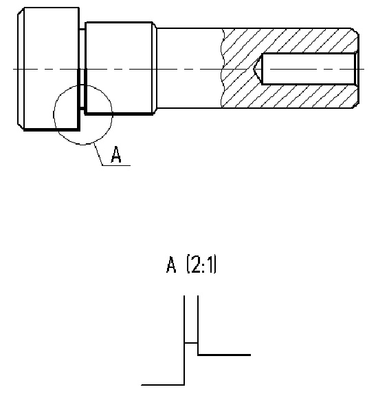
As a result of its use, the caption for the detail view is created on the drawing. The image of the detail view itself is automatically clipped by selected contour (circle, oval or rectangle) and augmented by the view caption. The obtained image can be edited later by using the standard tools of the T-FLEX CAD.

When creating the detail view with the caption, the following will occur:
1.Creating the new drawing view (on the basis of a new page of the type “Auxiliary”). The values of the parameters of the drawing view are set “by default”;
2.Creating a copy with translation for associated copying of the selected elements onto the drawing view page with the specified scale and rotation angle. Clipping the image to be copied by the automatically created hatch of the specified form;
3.Creating detailing elements for the detail view (view caption, caption of the detail view).
After calling the ![]() Detailed View command it is necessary to do the following:
Detailed View command it is necessary to do the following:
1.Select the fixing node for the elements which will be copied;
2.Specify the center of the selection area for the detail view;
3.Specify the form and size of the selection area for the detail view;
4.Specify the location of the leader line jog for the detail view caption;
5.Specify the location of the detail view (that is, the location of the drawing view with the detail view).
Note that in the described sequence of steps, there is no step for selecting the original elements to be copied. When creating the detail view with the caption, the collection of the copied elements is determined by the view selection area – all 2D elements at least partially contained in the specified area will be copied.
For selecting the fixing node, in the auto menu of the command the following option will be available:
|
<N> |
Set relation with Node |
The fixing node will determine the initial location of the fixing point for the created view. If, upon specifying the fixing node, the user selects an arbitrary point on the drawing (with the help of ![]() ), then at this point the free node, which will be selected as the fixing node, will be automatically created.
), then at this point the free node, which will be selected as the fixing node, will be automatically created.
After specifying the fixing node, the system will ask to specify the center of the selection area. This can be done by picking an arbitrary point in the drawing's window (with the help of ![]() ) or by specifying exact coordinates in the command's parameters window.
) or by specifying exact coordinates in the command's parameters window.
The center of the selection area can be also defined by selecting a 2D node or offset of the center point from the fixing node (selected at the previous step). For selecting the 2D node the following option is used:
|
<N> |
Set relation with Node |
For specifying the offset of the center of the selection area from the fixing node, the following option is used:
|
<A> |
Set Relative Position |
After selecting the center of the selection area, the form and dimensions of the area need to be specified.
The form of the area is specified in the command's parameters window: circle, rectangle, oval.
The dimensions of the area can be specified either in the parameters window or directly in the drawing's window (the dynamic image of the area's bounding frame will follow the cursor, pressing ![]() will fix the frame location).
will fix the frame location).


After specifying the view selection area, the location of the leader line jog for the view caption has to be defined. Dynamic image of the leader line jog will follow the cursor. Pressing ![]() in the drawing's area will fix the jog location. The jog location can be also specified in the command's parameters window (by specifying the coordinates of the starting point of the jog in the group “Basic parameters” of the parameters window).
in the drawing's area will fix the jog location. The jog location can be also specified in the command's parameters window (by specifying the coordinates of the starting point of the jog in the group “Basic parameters” of the parameters window).
For changing orientation of the jog for the view caption, the following auto menu option can be used:
|
<Z> |
Change leader line jog orientation |
After specifying the jog location, the dynamic image of the created detail view, attached to the cursor, will appear on the screen. The location of the view on the drawing has to be specified next, as described in the Position and Orientation of Drawing View section.
To make the caption of the detail view change its location according to the modifications of the drawing, it is recommended to snap the copied element to the 2D node.
Finish adjusting of view's location and size using the ![]() option .
option .
The last step of the detail view creation is the view outline creation. The system allows to define the outline after pressing ![]() .
.

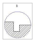
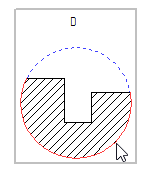
A dotted line appears around the selected area for the detail view. The line is divided into segments. A click into a segment enables/disables the display of the selected segment.

The following options are available:
|
<S> |
Show all segments of detail view outline |
|
<H> |
Hide all segments of detail view outline |
|
<I> |
Invert visibility of detail view outline segments |
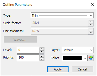
You can specify parameters for the outlines using the option ![]() .
.

For the constructed view, the caption will be automatically created. The obtained image can be edited and augmented, if required.
See Also: