Position and Orientation of Drawing View |
  
|
If a drawing view is being created with creation of a new page, view position and orientation can be defined using manipulators.
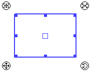
Special manipulators are provided, in order to define position, rotation angle and dimensions of a drawing view. All of them are handled in the similar way. Upon moving the cursor over a manipulator a tip appears indicating the type of transformations the manipulator is responsible for. Then you can apply such transformations in one of the following ways:
•Point and click
Press ![]() or <Enter> once and release. The manipulator will follow the cursor and the corresponding parameter of the view will change accordingly. Set the desired position of the manipulator and press
or <Enter> once and release. The manipulator will follow the cursor and the corresponding parameter of the view will change accordingly. Set the desired position of the manipulator and press ![]() or <Enter> again, in order to confirm the input.
or <Enter> again, in order to confirm the input.
•Drag and drop
Press and hold ![]() . Then move the cursor without releasing
. Then move the cursor without releasing ![]() . The manipulator will follow the cursor and the corresponding parameter of the view will change accordingly, as long as
. The manipulator will follow the cursor and the corresponding parameter of the view will change accordingly, as long as ![]() stays pressed. УSet the desired position of the manipulator and release
stays pressed. УSet the desired position of the manipulator and release ![]() , in order to confirm the input.
, in order to confirm the input.
|
View frame (whole picture movement and dimensions change) |
|
Manipulator of fixing point |
|
Manipulator of moving view area |
|
Manipulator of scaling |
|
Manipulator of moving whole picture |
|
Manipulator of rotation |
Fixing point of a drawing view is indicated by the ![]() manipulator. By default, the fixing point is at the center of the view. Upon calling the view creation command, the view frame dynamically moves so, that the fixing point coincides with the cursor position. Coordinates of the fixing point are indicated in the X and Y boxes of the Basic Parameters section of the parameters window.
manipulator. By default, the fixing point is at the center of the view. Upon calling the view creation command, the view frame dynamically moves so, that the fixing point coincides with the cursor position. Coordinates of the fixing point are indicated in the X and Y boxes of the Basic Parameters section of the parameters window.
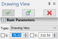
Set the desired position of the view in drawing either by placing the cursor over the desired point in 2D window, or by inputting coordinates via keyboard into the boxes of the parameters window, and press ![]() or <Enter>. The position of the view will be fixed.
or <Enter>. The position of the view will be fixed.
When specifying a view position in 2D window, you can snap it to 2D node or a characteristic point of a graphic line. In such case, an associative link is created between the view position and the specified object, i.e., upon further movements of the object, the view will move accordingly.
If you need to move the view again and utilize the coincidence between the fixing point and the cursor position, use the![]() manipulator in one of the ways described above.
manipulator in one of the ways described above.
if you need to move the view without the coincidence between the fixing point and the cursor position, use the whole picture movement, as described below.
If you need to change the position of the fixing point in relation to the view frame, press ![]() +<Shift> over the
+<Shift> over the ![]() manipulator. The position of the manipulator will become dynamically changing depending on the cursor position. By default, the manipulator snaps to the nearest characteristic point (angle or side center) of a view frame, or to a view center, depending on, what's closer to the cursor.If you need to snap the manipulator to an arbitrary point, hold <Ctrl> - as you hold it, the manipulator coincides with the cursor. Set the desired position of the manipulator and press
manipulator. The position of the manipulator will become dynamically changing depending on the cursor position. By default, the manipulator snaps to the nearest characteristic point (angle or side center) of a view frame, or to a view center, depending on, what's closer to the cursor.If you need to snap the manipulator to an arbitrary point, hold <Ctrl> - as you hold it, the manipulator coincides with the cursor. Set the desired position of the manipulator and press ![]() , in order to exit the fixing point selection mode.
, in order to exit the fixing point selection mode.
If a view is being created with creation of a new page, the position of the fixing point in relation to view frame can be specified using following automenu options:
|
Left Top |
|
Center Top |
|
Right Top |
|
Left Center |
|
Center |
|
Right Center |
|
Left Bottom |
|
Center Bottom |
|
Right Bottom |
|
Manually |
Upon activating the last option, the command switched to the fixing point coordinates defining mode. The coordinates can be defined either by typing values via keyboard into the X and Y boxes of the parameters window, or by pressing ![]() at the desired point of drawing window. Coordinates are specified withing the coordinate system of the current page, rather than the coordinate system of the view itself. Upon defining coordinates, confirm the input
at the desired point of drawing window. Coordinates are specified withing the coordinate system of the current page, rather than the coordinate system of the view itself. Upon defining coordinates, confirm the input ![]() (<Ctrl>+<Enter>), in order to return to the default mode of working with the command.
(<Ctrl>+<Enter>), in order to return to the default mode of working with the command.
The manipulator of view boundaries is the blue rectangular frame with square markers at angles and centers of sides. When the cursor is within the frame, its appearance changes to ![]() , which indicates, that the system is ready to move the view. Then you can move the view in one of the ways described above. Additionally, the
, which indicates, that the system is ready to move the view. Then you can move the view in one of the ways described above. Additionally, the ![]() manipulator of moving the whole picture is displayed near the left bottom angle of the frame. Upon moving the cursor over this manipulator, the cursor appearance also changes to
manipulator of moving the whole picture is displayed near the left bottom angle of the frame. Upon moving the cursor over this manipulator, the cursor appearance also changes to ![]() , so you can move the view in one of the ways described above.
, so you can move the view in one of the ways described above.
The Automatically Update View Border option is active by default, so dimensions of view frame and, therefore, view borders are defined by dimensions of view page (for usual drawing view) or by dimensions of view content (for detail view). Markers of the view frame allow to customize the dimensions of view frame and borders manually. Upon moving the cursor over a marker, the cursor appearance changes to ![]() ,
, ![]() ,
, ![]() or
or ![]() , which indicates, that the system is ready to change the indicated dimension. the you can change the dimension in one of the ways described above. Upon changing a dimension using a marker, the Automatically Update View Border option gets disabled automatically.
, which indicates, that the system is ready to change the indicated dimension. the you can change the dimension in one of the ways described above. Upon changing a dimension using a marker, the Automatically Update View Border option gets disabled automatically.
if the Automatically Update View Border option is disabled, the view frame can be moved in relation to the view content, using the ![]() manipulator of view area movement. Upon moving the cursor over this manipulator, the cursor appearance changes to
manipulator of view area movement. Upon moving the cursor over this manipulator, the cursor appearance changes to ![]() , so you can move the view in one of the ways described above.
, so you can move the view in one of the ways described above.
By default, the view frame coincides with the boundaries of the view page. Moving view area may be useful, when you need a view containing just some portion of the view page. In such case, you should enable the Use Clipping checkbox in view parameters; so the content of the view page outside the view frame won't be displayed in the view.
The resulting scale of the view content is defined by two interrelated parameters - page scale and view scale.
Detailed information on these parameters can be found in the Scale of Drawing View section.
The view scale can be changed using the ![]() scaling manipulator. Upon moving the cursor over this manipulator, the cursor appearance changes to
scaling manipulator. Upon moving the cursor over this manipulator, the cursor appearance changes to ![]() , so you can change the scale in one of the ways described above. Alternatively, the View scale value can be typed into the eponymous box of the parameters window. Pressing <W> activates this box. It also disables the Scale by fixing vector option.
, so you can change the scale in one of the ways described above. Alternatively, the View scale value can be typed into the eponymous box of the parameters window. Pressing <W> activates this box. It also disables the Scale by fixing vector option.
By default, the orientation of the view coordinates system coincides with the orientation of the coordinate system of the page the view is placed on. You can rotate the view, if necessary, using the ![]() rotation manipulator. Upon moving the cursor over this manipulator, the cursor appearance changes to
rotation manipulator. Upon moving the cursor over this manipulator, the cursor appearance changes to ![]() , so you can change the scale in one of the ways described above. Alternatively, the Rotation angle can be typed into the eponymous box of the parameters window. Pressing <Q> activates this box.
, so you can change the scale in one of the ways described above. Alternatively, the Rotation angle can be typed into the eponymous box of the parameters window. Pressing <Q> activates this box.
If a view is based on an existing page containing a fixing vector, such vector may be used for positioning the view.
Enable the Fixing Vector checkbox in the command's parameters window and select the desired vector in the drop-down list below. The fixing point manipulator will be replaced by the fixing vector manipulator, so you'll have to specify a one (if the vector uses a single point only) or two (in general case) points defining the origin and the end of the vector, same as when inserting a 2D fragment.
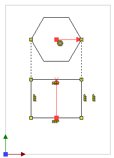
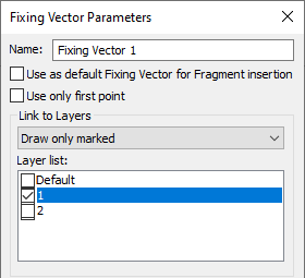
View page.
Upper fixing vector is linked with the layer the hexagon belongs to,
lower fixing vector is linked with the layer the rectangle belongs to.
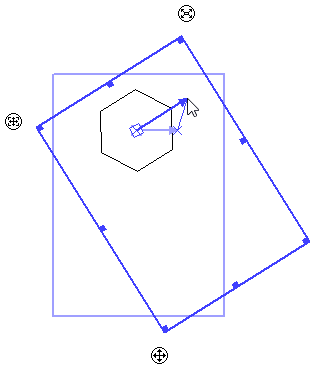
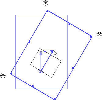
Left - positioning of the view using the first vector, right - using the second vector.