Boundaries of Drawing View |
  
|
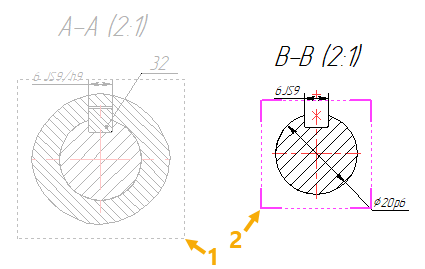
Boundaries of drawing views and detail views are indicated by dashed rectangular frames in drawing window. These frames are non-printable. They can be used for selection and activation of views.
By default, boundaries of a usual drawing view are defined by dimensions of its page (so if some content of the view is beyond the page limits, it will be outside view boundaries), and boundaries of a detail view are defined by automatically in accordance with the size of view content. If you disable the Automatically Update View Border option in contextual menu of a view, then boundaries of the view will be defined manually by the view frame manipulator.
By default, the content of the view is displayed, regardless of whether it fits its boundaries. If you enable the Use Clipping checkbox in view parameters, the content outside the boundaries won't be displayed in the view.
By default, boundaries of non-active and non-selected views are shown in gray color, and boundaries of active or selected views are shown in magenta. Color of boundaries can be changed in the Colors tab of the system options dialog. Boundaries color of non-active and non-selected views is managed by the Drawing Views with Breaks > Limits of inactive drawing view parameter, of active views - by the Common > Active Projection parameter, of selected views - by the 2D Elements Highlighting > Other Elements Highlighting parameter (the last parameter also defines colors of selected elements of some other types, e.g. drawing detailing elements).
The ![]() Hide/Show Construction command, handles the visibility of boundaries of inactive drawing views and 2D projections, among the other things. moreover, regardless of the status of this command, you can disable the boundaries display for a particular view by disabling the Show Border checkbox in view parameters.
Hide/Show Construction command, handles the visibility of boundaries of inactive drawing views and 2D projections, among the other things. moreover, regardless of the status of this command, you can disable the boundaries display for a particular view by disabling the Show Border checkbox in view parameters.

1 - Boundaries of inactive view
2 - Boundaries of active view