Drawing View |
  
|
Drawing views are created using the command “Create Drawing View”:
Icon |
Ribbon |
|---|---|
|
Draw > Draw > Drawing View Sheet Metal (2D) > Draw > Drawing View |
Keyboard |
Textual Menu |
<SD> |
Draw > Drawing View |
This chapter describes an auxiliary element of T-FLEX CAD system – the drawing view. Additional views, detail views, local section views and sections – all these instances are supported by Drawing View. This functionality handles situations when elaboration to the images on the main views is required. This can be an additional view, and, in particular, a scaled view. The functionality allows collecting together on one page elements from different pages, inserting an image (or a portion thereof) from one page into another page in various scales, even create a simple assembly from parts contained in the same document.
Main concepts
A drawing view is an element of T-FLEX CAD that allows displaying contents of one page (or a portion thereof) on another page, scaled to the necessary factor. It is a rectangular area of specified size used for displaying the contents of another page.
The page displayed within a drawing view can either be selected from the list of existing pages in the document or additionally created for the drawing view. The newly created page is assigned the type "Auxiliary". A drawing view can be nested, that is placed within another drawing view.
Location of the drawing view box on the main page can be specified by either direct selection of the fixing point and the view rotation angle or with the help of the fixing vector located on the view page.
The main purpose of a drawing view is to display on one page drawing elements of different scales. For example, one can create a drawing of some object on one page and then create drawing views of this object on other pages that will display portions of this drawing to various scales.
Besides, drawing views can be used simply for collecting the contents from different pages. This may be used for adding to the main drawing some additional, local views and sections created on other document pages in different scales. This capability is the most common way of using drawing views in T-FLEX CAD. Note that the images on the detail views can be copied from other pages of the current document when the drawing view is created (see section “Creating Detail View”), and enhanced with captions of the view notations (see section “Creating Detail View with Caption”).
|
|
Detail View |
Detail View with Caption |
The image displayed on a drawing view can be created or edited either on the original page of the drawing view elements, or directly in the view area of the main page by activating the view.
Limits are shown on the drawing for drawing view and detail view. The limits are not printed. If you want to change color of the limits use the option Limits of inactive drawing view on the Color tab in the Set system options command. You can specify colors of the other drawing view elements on the tab.
Types of drawing views
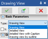
After invoking this command, the following options will appear in the auto menu:
|
<О> |
|
|
<V> |
|
|
<С> |
|
|
<S> |
These options define different modes of creating drawing views.
These command operation modes can be also specified in the parameters window. The command's parameters window and the automenu work synchronously.

The following automenu option is available, when creating and editing drawing views:
|
<B> |
Add or edit Broken View |
Breaks of drawing views are handled in the same way as breaks of 2D projections. The detailed information can be found in the Breaks of Projections and Drawing Views section.
Topics in this section:
•Position and Orientation of Drawing View
•Create Detail View by Elements
•Create Detail View with Caption
•Create Detail View by Contour
•Parameters Dialog of Drawing View
•Contextual Menu of Drawing View