Create Drawing View |
  
|
Create Drawing View |
|
Usual drawing views can be created using the following automenu option of the Drawing View command:
|
<О> |
New Drawing View |
This option is active by default, upon calling the command.
Upon option's activation, you should specify a page for the resulting view to be based upon. Following variants are available in the Drawing View section of the command's parameters window:
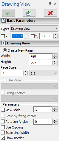
•Create New Page
A new page of the Auxiliary type will be created along with a new drawing view.
The created page will not contain any elements. The user is supposed to create the necessary contents on this page himself. The editing techniques of drawing views and their contents are described in the section “Editing drawing views”.
Following specific parameters are available, when creating a new page:
oWidth and Height
Define the page size. These also define the initial size of the drawing view boundaries.
oPage Scale
Defines the scale factor of the view page.
Specified values will be saved in document parameters for the resulting view page (Document Parameters > Page > Paper).
•Use Existing Page
Allows selecting any existing page in the document (except the current one) from the list. This parameter is inaccessible for one-page documents. The size of the drawing view boundaries is automatically set in accordance with the size of the selected page.
If the selected page contains fixing vector, the following option will be available:
oFixing Vector
Enabling this option allows the user to select in the drop-down list below any of the fixing vectors existing on the selected page and use it for snapping the created drawing view. .
Fixing Vector can be used for placing a drawing view, just like a 2D fragment. This also allows controlling the view page layers visibility as the page is displayed on a view. Usage of fixing vectors is described in details in the chapter Assembly Drawing.
Upon specifying a page, specify the view position and orientation, as described in the Position and Orientation of Drawing View section.
Additionally, you may use the following options available in the Parameters group in the parameters window:
•Drawing Scale
Scale of displaying the view content on the page the view is placed on.
Detailed information on scales can be found in the Scale of Drawing View section.
•Scale by fixing vector
If the checkbox is enabled, the value of the Drawing Scale parameter is calculated automatically, as the ratio between the specified length of the fixing vector and its initial length.
•Rotation Angle
Angle of rotating the view around its fixing point. The positive angle direction is counterclockwise. When using fixing vector for view positioning, angle value is non-editable, as it is defined by the specified vector.
•Clip Image
If the checkbox is enabled, the content of the view page outside the view boundaries is not displayed in the page the view is placed on.
•Scale Lines
If the checkbox is enabled, thickness of graphic lines in the view is scaled in accordance with the value of the Drawing Scale parameter.
•Show Border
If the checkbox is enabled, view boundaries are displayed, regardless of whether the view is active or not. If the checkbox is disabled, view boundaries are displayed only for active view.
Hiding the constructions hides boundaries of inactive views, regardless of the status of this checkbox.
Finish the input (![]() or <Ctrl>+<Enter>), in order to complete view creation. As a result, a rectangular area of the drawing view will be created, with the contents of the specified page or its portion displayed within.
or <Ctrl>+<Enter>), in order to complete view creation. As a result, a rectangular area of the drawing view will be created, with the contents of the specified page or its portion displayed within.