Three Standard Views |
  
|
The command can be called in one of the following ways:
Icon |
Ribbon |
|---|---|
|
Draw > Projection > Three Standard Views Assembly (3D) > Additional > Three Standard Views Sheet Metal (2D) > Draw > Three Standard Views Weld > Additional > Three Standard Views |
Keyboard |
Textual Menu |
<3КJ> |
Draw > 2D Projection > Three Standard Views |
It is also available as option in the 2D Projection command:
|
<1> |
Three Standard Views |
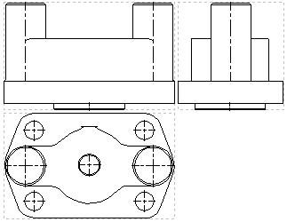
The command creates three standard projections linked with each other. The set of resulting projections depends on the standard selected in system options (Options > 3D > Projections > Position of projection views). The ISO standard is selected by default, so the command yields Front view, Left view and Top view. The Front view is the main view, which defines positions of two other views. The Left view is located to the right of the front view, the Top view - below the front view. Upon changing the standard to ANSI, the command yields the Right view instead of the left one and the Bottom view instead of the top one; their positions in relation to the main view stay the same.
Standard projections coincide with eponymous standard view points of camera in 3D scene.

When creating standard views, the automenu has several additional options common for all types of projection (options for creating broken views and handling sections). Working with those will be described separately.
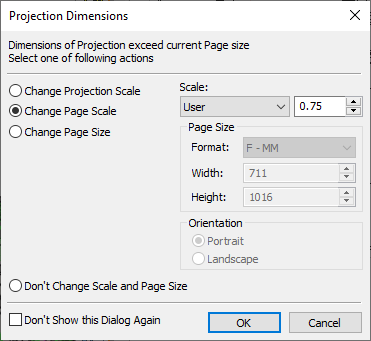
If overall size of a projection exceeds the page size, system will open the dialog box with options for correcting inconsistency between the projection and the page. The dialog box offers the following options:
•Change projection scale;
•Change page scale;
•Change page size;
•Don’t change anything.
All correctional parameters are calculated automatically. User can agree with them or set custom values.

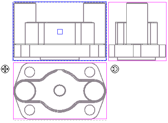
Next, you need to position the projections on the drawing. Three pink frames appear in the 2D window, attached to the pointer. These frames mark the extents of the projections being created. Currently, all three projections are selected. Position a particular view, selected first.


View selection is done by clicking once within the pink box or by selecting an item in the combo box in the parameters window. After selecting a projection, you need to select the fixing point in the 2D view. Click ![]() , and the projection will be attached to the position of the pointer. The option of positioning a view allows fixing a projection to an unconstrained point (right under the click) or to a 2D node.
, and the projection will be attached to the position of the pointer. The option of positioning a view allows fixing a projection to an unconstrained point (right under the click) or to a 2D node.

The mechanism of positioning a projection on the drawing is common to all types of projections; therefore, we will skip its detailed description in the future.
If the front (main) view is being positioned, the rest of the views maintain their position with respect to the main one. When adjacent views are positioned, the projective relation is maintained with respect to the main view. The projection centerpoint snaps to the attachment point. If you need to align the attachment point with a specific element of the 3D model (3D node or vertex), then you should create a projection using the set of additional tools in the 2D Projection command.
By default, the adjacent views maintain the projective relation with the main view.
Identical parameters are set for all views created simultaneously. In the case when different settings are required for a particular view, select it in the parameters window. After that, you can define the specific elements to be projected on this view or select a 3D section to be used on the view. In some cases, this approach to creating views can save time.
See Also:
•Algorithm of Creating 2D Projection
•General Parameters of 2D Projection
•Position of 2D Projection on Drawing
•Additional Parameters of 2D Projection
•3D Model Elements on 2D Projection
•2D Projection by External Model
•Parameters of Sections on 2D Projection