Creating DOCs Objects of Different Geometry Based on Same CAD File |
  
|
Association of T‑FLEX DOCs parameters with T‑FLEX CAD variables can be utilized, while working with parametric models in the T‑FLEX DOCs window. In this case the same file of the T‑FLEX CAD parametric model is linked to multiple objects of T‑FLEX DOCs dataset, and when T‑FLEX DOCs parameters are changed, model geometry changes too.
To make this possible, name of the T‑FLEX CAD variable must be the same as the name of database field which corresponds with required T‑FLEX DOCs parameter.
Only administrator user can review names of T‑FLEX DOCs fields in the database.
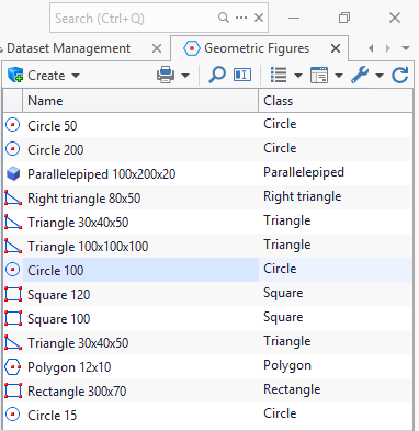
As an example, we use the Geometric figures custom dataset. In this dataset user can create various figures of required dimensions based on prototypes: rectangle, square, circle, etc.

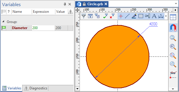
Each prototype has T‑FLEX CAD file with corresponding drawing attached. In T‑FLEX CAD size of the figure is set with variable. E.g. for Circle object type diameter is set via the Diameter variable, which will have value 200 by default. In this case, name of the variable coincides with the name of the filed in the database which corresponds to Diameter T‑FLEX DOCs parameter.

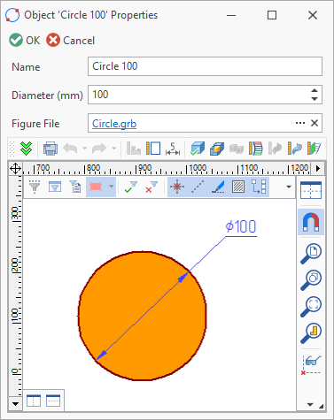
When creating a new dataset object of Circle type from prototype, it will also have this file attached, but in the object properties window user will set new value for circle diameter. Then the circle will be displayed in the T‑FLEX DOCs window with new diameter value.
Attached T‑FLEX CAD file will remain the same.

This T‑FLEX DOCs function can be used for creation of graphic images and models for catalogs. E.g. catalog of tools or products with basic dimensions.