3D Offset Curve to 3D Path |
  
|
The command can be called in one of the following ways:
Icon |
Ribbon |
|
Support Geometry > 3D Path > 3D Offset Curve to 3D Path |
Keyboard |
Textual Menu |
<3KCP> |
|
Automenu of the |
|
<D> |
3D Offset Curve to 3D Path |
To create a 3D path as a 3D offset, all you need is just to select the source 3D path (of any shape), the offset distance and offsetting direction. The offsetting direction will define the direction of offsetting each point of the source path. A 3D spline will then be constructed, uniting all such points created by offsetting.
A 3D path created as a 3D offset can be used, for example, in CAM processing for creating tool movement trajectories accounting for the tool radius correction; also, in diecast mold design for creating the separation surface (using the outline edge and an offset to it).
There are two ways of defining the offset direction:
•Direction vector. A single direction vector is defined for the whole offset – by two 3D points, a straight edge, a normal to a flat face or workplane.
To yield the offset, each point of the source 3D path is shifted by the specified distance along the vector defined as the cross product of the tangent to the path at the given point and the specified offset direction vector. That means, a point being offset is shifted in the direction perpendicular to both the direction vector and the tangent to the source path.

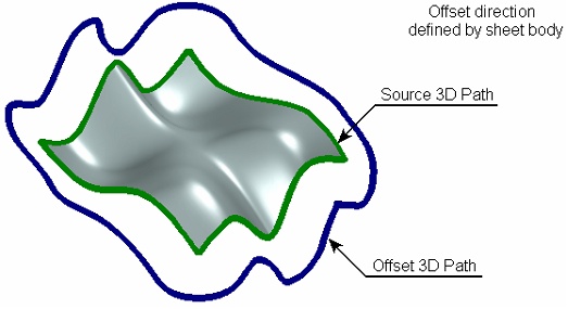
•Direction from body. This way of creating a 3D offset implies creation of a 3D Path as a "continuation" of a sheet body surface (tangentially). The offsetting direction is defined by the operation body, whose surface needs to be extended. The source 3D path must lie on the same body.
We recommend using a sheet body that lies in one surface, while the source path – a 3D path constructed along the bounding edges of this sheet body. Use of other configurations of the source data leads to an undetermined result of the offset creation.
To make the offset, each point of the source 3D path is shifted by the specified distance along the vector defined as the cross product of the path tangent and the normal to the guiding surface at this point.

An additional provision of offset with rotation can be used together with any method of creating an offset. In this mode, the offset vector calculated for each point of the source path is additionally rotated about the path tangent at that point by the specified angle. The 3D offset with rotation can be useful, for example, in CAM operations – for constructing a guide path defining the tool inclination angle.

The first step in creating the 3D offset curve is selection of the source 3D path by the option:
![]() <A> Select 3D Path
<A> Select 3D Path
After that, you need to define the offsetting direction.
To define the direction by the direction vector, the following options are used:
![]() <B> Select first Point of Direction
<B> Select first Point of Direction
![]() <C> Select second Point of Direction
<C> Select second Point of Direction
![]() <D> Select straight Direction
<D> Select straight Direction
The first two options (![]() and
and ![]() ) allow defining the direction vector by two 3D points. The option
) allow defining the direction vector by two 3D points. The option ![]() serves to select a 3D object suitable for defining the direction vector at once.
serves to select a 3D object suitable for defining the direction vector at once.
To define the offset direction from a body, use the option:
![]() <G> Select Solid Body
<G> Select Solid Body
The offset amount is specified in the command parameters window or in the path parameters dialog (the option ![]() ).
).
The shift of the offset is specified in the "Distance" parameter. Here, the offset with rotation mode can also be turned on (if necessary). For this, simply enter the desired value of the rotation angle in the field of the "Angle" parameter (the default value is set to "0").

See Also: