Offset Curve to 3D Curve on Surface |
  
|
The command can be called in one of the following ways:
Icon |
Ribbon |
|
Support Geometry > 3D Path > Offset Curve to 3D Curve on Surface |
Keyboard |
Textual Menu |
<3KCS> |
|
Automenu of the |
|
<U> |
Offset Curve to 3D Curve on Surface |
To create a 3D path as an offset to a 3D curve on a surface, select the source curve – a 3D path. The offset will be constructed by shifting the points of the original curve by the specified distance along the surface of the face on which the source curve lies. The source 3D path must necessarily lay on a face of a body.
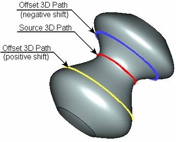
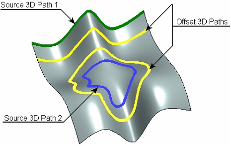
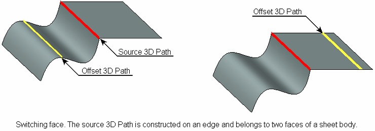
The face on which the selected 3D path lies is defined by the system automatically. Whenever possible, the user is offered to change the system selection (for example, if the 3D path was created on an edge dividing two faces of a body).
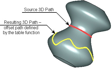
Shifting the offset from the source curve can be defined by a numerical value or by a tabulated function. The table definition of the shift distance allows creating an offset with variable shift from the source curve. The shift table determines the position of control points on the source path and their respective shift values.
The accuracy of constructing the resulting 3D path is defined either by the number of points, through which the path is created, or by the offset tolerance. When using offset tolerance, the path is constructed in such a way that the resulting curve-to-chord distance for any given pair of sequential points does not exceed the specified accuracy value. The more use the number of points set for the offset or the higher use the specified accuracy, the more precisely the offset path will be constructed.
Upon calling the command, select the source 3D path by the option:
![]() <Z> Select path on surface
<Z> Select path on surface
The offset value and curve's construction accuracy are defined in the parameters window or in the path parameters dialog (the option ![]() ).
).
To define an offset by a numerical value, select the Constant option in the Offset Type drop-down list and enter the desired value in the Offset input box. To use a variable offset, select the Function option in the Offset Type drop-down list. Variable offset can be defined individually for each point of the initial curve depending on the position of such point on the curve's length. The offset - length dependency is set in the offsets table.
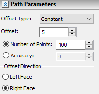
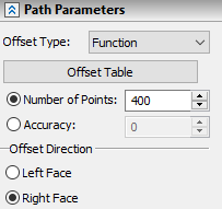
Upon selecting the Function option the Offset input box gets replaced by the Offset Table button. The button invokes the Offsets dialog.
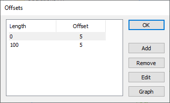
The left side of the Offsets dialog contains the offsets table, the right side - table editing buttons.
To add a new row, click the Add button. The Offset dialog will appear on the screen. In it, specify the position of the new control point (the Length parameter) and the value of its offset (the Offset parameter).
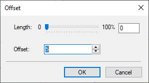
The Offset dialog is also used for editing an existing row in the table, upon clicking the Edit button.
The Delete button allows deleting the selected row from the table.
The offset - length dependency can be also defined via a graph. To do this, use the Graph button. Clicking this button invokes the graphs editor.
The detailed in formation on working with graphs an be found in the Graphs chapter.
The accuracy of constructing the resulting path, may be defined either by the Number of Points or by the Tolerance value. Select one of these parameters in the parameters window and type in its value.
The face on which the offset is being created can be change by the option:
![]() <Tab> Select other adjacent Face
<Tab> Select other adjacent Face
The Offset Direction switch in the parameters window can be used for the same purpose.
See Also: