Offset Curve to Planar 3D Path |
  
|
Offset Curve to Planar 3D Path |
|
The command can be called in one of the following ways:
Icon |
Ribbon |
|
Support Geometry > 3D Path > Offset Curve to Planar 3D Path |
Keyboard |
Textual Menu |
<3KCF> |
|
Automenu of the |
|
<F> |
Offset Curve to Planar 3D Path |
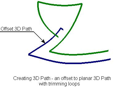
To create a path - an offset to a planar 3D path, select the source path and specify the shift with respect to the source 3D path. The shift can be defined in two ways:
By specifying a 3D node through which the offset should pass. The node must lie in the plane of the source path. By a numerical value of the shift of the offset path from the source path. The figure presents an example of creating an offset path with the shift defined by a 3D node.

Creating this kind of a path is similar to creating a 3D profile as an offset to another planar 3D profile (see the chapter "3D profiles").
The gaps introduced between the segments of the offset path can be processed in three ways:
Natural – the curves making up the source path are continued. Straight lines are continued straight, arcs are rounded up.
Round – a fillet is created between the end points of the neighboring segments of the path being created.
Extend – straight lines are added to the hanging points that are tangent to the path segments at the gaps.


Natural Round Extend
When creating an offset to a path of the complex shape, self intersection loops may occur in the contour of the new path. An additional loop trimming mode helps removing those automatically.

The first step in creating the 3D path is selecting the source planar 3D path by the option:
![]() <T> Select planar 3D Path
<T> Select planar 3D Path
After that, one has to specify the required shift by a 3D node or numerical value. The 3D node is selected by the option:
![]() <N> Select 3D Vertex in the plane of selected path
<N> Select 3D Vertex in the plane of selected path
To reject a selected node, you can use the option:
![]() <K> Cancel Node selection
<K> Cancel Node selection
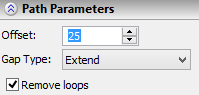
The numerical value of the shift is specified in the command's parameters window. Here, other offset parameters are defined as well. The option of processing gaps introduced by creating the offset path is defined by the parameter "Gap Type". The mode of deleting loops turns on upon setting the flag "Remove loops".
See Also: