3D Node |
  
|
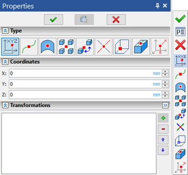
The command dialog was updated. Options for creating a 3D node are divided into 9 types. Each type has a corresponding icon in the dialog that is duplicated in the command automenu.

As in all renewed dialogs, creation modes can be selected by clicking the icon at the top of the dialog.
|
In Coordinates |
|
On Path |
|
On Surface |
|
In Center of Mass |
|
By Shortest Distance |
|
On Intersection of Elements |
|
On Intersection of Three Planes |
|
By Faces and Offsets |
|
By Two Projections |
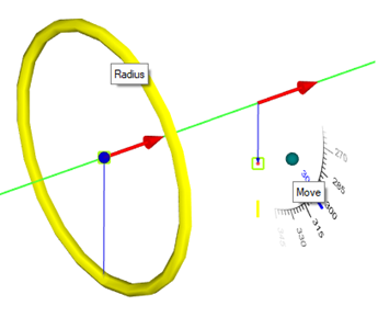
On Path. Draggers that enable you to set the position of a 3D node in a cylindrical coordinate system whose axis is tangent to the path were added. The position of the point of contact of the axis with the path is determined by the parameter "U", which changes in the selected system of units according to the total length of the path. The "R" parameter specifies the radius, and the "V" parameter specifies the angle. You can also change the units of measurement for these parameters.

On Surface. Draggers that enable you to move a node along the surface, as well as set the node offset along the normal to the surface, were added. The offset on the surface is set by the parameters "U" and "V" which lie in the interval from 0 to 1. The normal offset is set by the "W" parameter in the specified length units.
By Shortest Distance. The segment of the shortest distance is determined between the elements. A 3D node will be placed on it. This segment is not shown explicitly in the 3D scene. Using the Ratio parameter, you can determine the position of the 3D node on the specified segment in the range from 0 to 1.
Bindings are now available for 3D node manipulators.