3D Path |
  
|
Helix 3D Path
New types of helix 3D path have been added:
Isoparametric curve
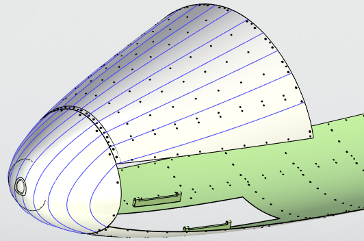
A new option for creating 3D paths has been added to the command: Isoparametric Curve.

You can create a grid consisting of separate 3D paths on the selected surface. The grid can be created in one or two directions. You can specify a step for the grid. You can set the step for creating isoparametric paths based on values entered by the user or based on 3D points. 3D points can be specially created by the user or set based on an existing body. You can use isoparametric curves as the initial and final segments of transition paths, along which you can create a surface.
Conic Curve
Conic Curve is the new mode for building a 3D path. It is essentially a separate command that enables you to create the spatial curves of a conic section: hyperbola, parabola, arc of an ellipse. The mode is directly related to the new Transition Surface command, where the forming surface profile is also a conic section curve. New wire and surface modeling tools expand possibilities for working with structures where aerodynamic properties are important: curves and surfaces of a conic section are widely used in aviation as geometric objects with optimal curvature.
The new Conic Curve 3D path option was added. It has six options for creating a conic curve. You can select an option by clicking the corresponding dialog icon.
|
By 5 Points |
|
By 2 Points, 2 Guides and Discriminant |
|
By 3 Points and 2 Guides |
|
By 2 Points, Vertex and Discriminant |
|
By 3 Points and Vertex |
|
By 4 Points and Guide |
The command dialog enables you to edit the selected construction elements.
The resulting curves will represent 3D paths for which all possible wire geometry operations will be available, and which can be used as construction elements in solid-state and surface modeling operations.
Transition Path
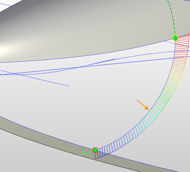
The functionality of the option for creating transition paths has been expanded. Tangent settings are available for the transition path in the Spline mode: for each endpoint, the smoothness types G0, G1, G2, and G3 are available. The length of the tangent vector is determined by the Tangent magnitude parameter.

The transition path can be "put" on the selected surface using the Select Supporting Geometry ![]() option.
option.
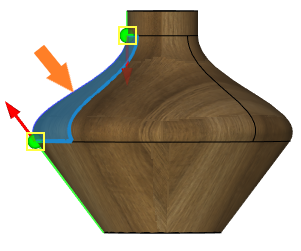
Connecting curve along supporting faces
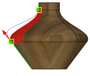
Added the ability to create a connecting curve for a set of supporting faces.
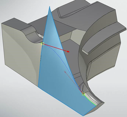
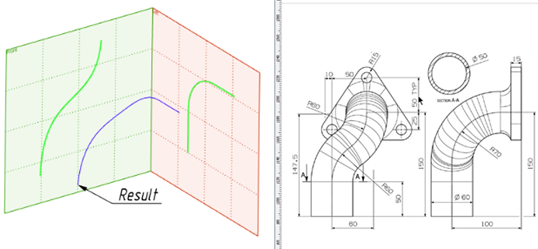
3D Path by Two Projections
The Create 3D Path using two projections option features were extended. Now the condition for coincidence of start and end points of the projections is not mandatory. When working from 2D to 3D, you can select image lines.
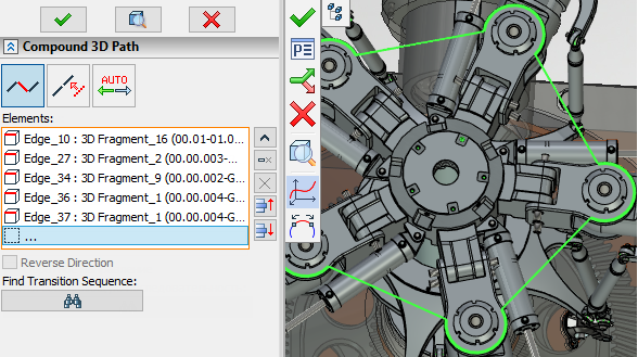
Compound 3D Path
The mechanism for creating paths on multiple 3D paths and multiple edges was improved and optimized. Now you can create such paths in the same Compound 3D Path mode. A smooth sequence of paths and edges can be selected automatically when one of the sequence elements is selected. When you select unrelated elements, there are several ways to join them: Auto Joining Mode, Move. When you select Auto Joining Mode, the elements are automatically joined by line segments. When you select the Move mode, the start point of the next section is moved to the endpoint of the previous one.
The Auto mode is also available. In this mode, only joined elements can be selected, and the orientation of elements that are included in the path is determined automatically, as it worked before.
|
Auto Joining Mode |
|
Move |
|
Auto |
All the selected elements must be single linked, i.e. you cannot select different ways to link elements when creating a single path.
Modification
The path modification command can be called from the Ribbon in the Path list: Change 3D Path Length and Smooth 3D Path.
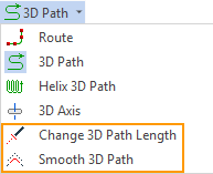
You can also call the Modify command from the path context menu.
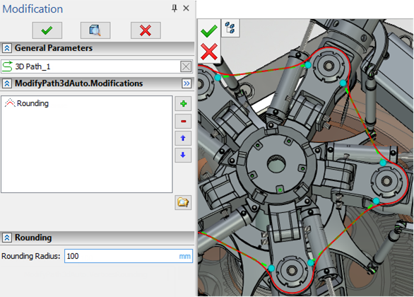
Smooth 3D Path allows you to round all sharp edges on the path, and Change 3D Path Length allows you to set the law of lengthening the path from its extreme points or change the total length of the path to a specified value. You can change the length symmetrically on both sides or specify an invariable side.
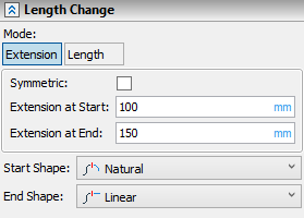
You can select only one smoothing modification and one length change modification for each path. Modification options can be added using the icon ![]() .
.
![]()
When you call the modification command again, the parameters of the previous modification will already be set for the path in the dialog. You can change the modification parameters, or you can delete one of the two modification options ![]() or both modification options at once.
or both modification options at once.
3D Path by Function
A new command 3D Path by Function has been added, which allows you to create a 3D path by function in a given coordinate system.
There are 3 types of coordinate systems available - Cartesian, Cylindrical, Spherical. Each coordinate system has its own set of parameters. So, for example, for a Cartesian coordinate system it is proposed to specify formulas for X, Y, Z, for cylindrical with respect to ρ, φ, Z, and for spherical with respect to ρ, θ, φ.
For all types of coordinate systems, it is possible to select, create and delete a type of function.
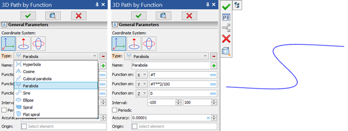
For each type of coordinate system, it is possible to set the interval, accuracy and select the origin of the 3D path. You can also close the 3D path using the Periodic option.