3D Profile by 2D Elements |
  
|
The command can be called in one of the following ways:
Icon |
Ribbon |
|
3D Model > Construct > 3D Profile by 2D Elements Sheet Metal (3D) > Construct > 3D Profile by 2D Elements Surfaces > Construct > 3D Profile by 2D Elements Weld > Construct > 3D Profile by 2D Elements Primitives > Construct > 3D Profile by 2D Elements Support Geometry > 3D Profile > 3D Profile by 2D Elements |
Keyboard |
Textual Menu |
<3KRF> |
Construct > 3D Profile > 3D Profile by 2D Elements |
Automenu of the |
|
<H> |
3D Profile by 2D Elements |
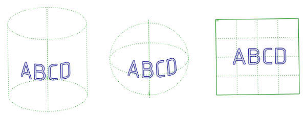
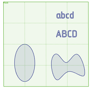
3D profiles based on 2D elements are widely used in all stages of 3D modeling. Profiles can be based on graphic and sketch lines, hatches of any type, and texts written in TrueType fonts (such fonts are indicated by the ![]() icon). 2D elements for 3D profile creation may lay on workplanes or worksurfaces. Elements laying on a workplane produce a flat profile. Elements laying on a worksurface produce a spatial profile following the shape of a worksurface.
icon). 2D elements for 3D profile creation may lay on workplanes or worksurfaces. Elements laying on a workplane produce a flat profile. Elements laying on a worksurface produce a spatial profile following the shape of a worksurface.
Text written in TrueType font (![]() ) is considered a union of closed contours, where each contour is a separate character. Thus, the resulting 3D profile is a multi-contoured. Elements of a text that cannot be transformed into the profile contour lines are ignored. For example, if a roughness symbol was inserted in a text, then only letters and numbers in the roughness notation will be used for generating the contour lines, while the strokes of the roughness symbol itself will be ignored.
) is considered a union of closed contours, where each contour is a separate character. Thus, the resulting 3D profile is a multi-contoured. Elements of a text that cannot be transformed into the profile contour lines are ignored. For example, if a roughness symbol was inserted in a text, then only letters and numbers in the roughness notation will be used for generating the contour lines, while the strokes of the roughness symbol itself will be ignored.
3D profile creation modes
Following ways of creating 3D profile by 2D elements are available:
•![]() by elements;
by elements;
•![]() by color;
by color;
It is also possible to set an additional snap.
![]() Creating 3D profile by elements
Creating 3D profile by elements
In this mode 3D profile is created from manually selected 2D elements of the same type belonging to the same workplane or worksurface.
The mode is activated using the By Elements button located in the top of the Parameters window. Then you need to select Source Elements. Elements can be selected either on an active workplane (worksurface) or in the Model Elements window.
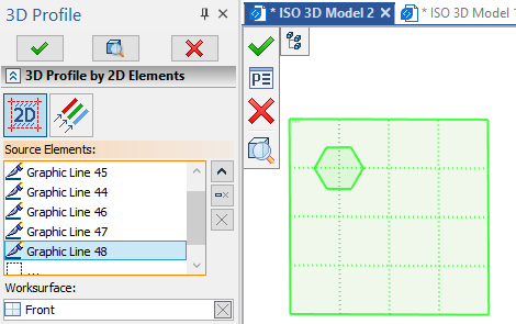
The list of selected Source Elements is displayed in the Parameters window. You can Expand ![]() , Collapse
, Collapse ![]() , Clear
, Clear ![]() the list or Delete Element from the List
the list or Delete Element from the List ![]() using buttons located on the right side.
using buttons located on the right side.
By default the system tries to auto-detect a worksurface which supports selected 2D elements. The Worksurface is displayed in the eponymous field of the Parameters window and can be Cleared ![]() and re-selected manually.
and re-selected manually.
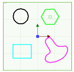
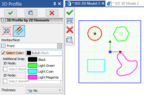
In this mode 3D profile is created by automatically selected 2D elements of the same color belonging to the same workplane (worksurface).
This mode is applicable to graphic lines only.
The mode is activated using the By Color button located in the top of the Parameters window. Then you need to select a workplane (worksurface) using the ![]() in the 3D scene or in the model tree. The selected Worksurface is displayed in the eponymous field of the Parameters window and can be Cleared
in the 3D scene or in the model tree. The selected Worksurface is displayed in the eponymous field of the Parameters window and can be Cleared ![]() and re-selected. Upon selecting a worksurface, it is necessary to Select Color of elements to be used for profile creation. Color can be selected from the drop-down list which opens upon clicking the color sample icon and contains all colors used on this worksurface. You can also type in RGB components values manually separating them by a comma.
and re-selected. Upon selecting a worksurface, it is necessary to Select Color of elements to be used for profile creation. Color can be selected from the drop-down list which opens upon clicking the color sample icon and contains all colors used on this worksurface. You can also type in RGB components values manually separating them by a comma.
![]() Automatic 3D profiles creation
Automatic 3D profiles creation
This mode doesn't require to use the 3D Profile creation command. 3D profile is created automatically upon exiting the active workplane mode if at least one suitable 2D element is drawn on such workplane (worksurface). The principle of automatic 3D profiles creation depends on type of elements drawn on workplane:
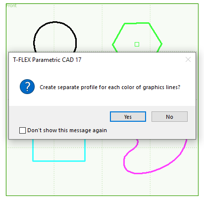
•If only graphic lines are present on an active workplane, the system automatically uses them for profiles creation. When lines are drawn in multiple colors, the system asks if it should create separate profile for each color of graphic lines. Upon negative answer a single profile is created from all lines of the active workplane regardless of their color. Upon positive answer several profiles are created and a color of each profile corresponds to a color of lines used for its creation.
If new lines are added to workplane after profiles creation, the system automatically adds such lines to existing profiles. You can see which color of lines was used for a particular profile in the 3D profile parameters dialog.
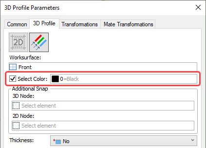
Color can be manually reselected or even cleared by disabling the Select Color checkbox. Upon clearing the color, the profile is regenerated using all graphic lines existing on this workplane (worksurface). Thickness should be applied if lines are intersecting or bifurcated.
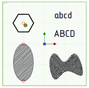
•If hatches or texts are present on the active workplane, the system only uses them for 3D profiles creation ignoring graphic lines. Each hatch and each texts is considered a separate profile.
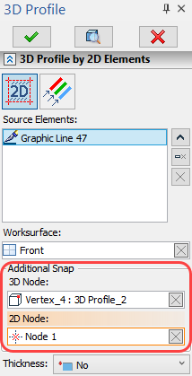
By default a 3D profile based on 2D elements lays on a same workplane as those elements. However you can manually select a 3D Node, so that profile will lay in a plane passing through such node and parallel to the plane of 2D elements. Additionally you can change a position of a profile by selecting a 2D Node on a plane of 2D source elements. The point of the profile corresponding to the selected 2D Node will coincide with the selected 3D Node.
|
Additional Snap is not applied |
|
The 3D Node is selected |
|
The 3D Node on the arbitrary plane and the 2D Node on the plane of source elements are selected |
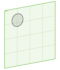
2D Node can also be selected on an arbitrary plane. In that case the distance between projection of source 2D elements onto profile's plane and resulting 3D profile itself is equal to the the distance between 3D node and projection of 2D node onto profile's plane.
|
|
Black circle - source 2D element Blue circle - resulting 3D profile 3D - 3D node 2D - 2D node |
Selected 2D and 3D Nodes are displayed in eponymous fields of the Parameters window and can be Cleared ![]() and re-selected.
and re-selected.
See also: