3D Profile by 3D Elements |
  
|
The command can be called in one of the following ways:
Icon |
Ribbon |
|
3D Model > Construct > 3D Profile by 3D Elements Sheet Metal (3D) > Construct > 3D Profile by 3D Elements Surfaces > Construct > 3D Profile by 3D Elements Weld > Construct > 3D Profile by 3D Elements Primitives > Construct > 3D Profile by 3D Elements Support Geometry > 3D Profile > 3D Profile by 3D Elements |
Keyboard |
Textual Menu |
<3KRV> |
Construct > 3D Profile > 3D Profile by 3D Elements |
Automenu of the |
|
<L> |
3D Profile by 3D Elements |
This type of 3D profile is based on existing 3D elements of a model. Geometry of a profile is fully defined by selected 3D elements as changes upon changing such elements. Profiles of this type can be flat or spatial.
3D Profile creation modes
Depending on source 3D elements there are different modes of 3D profile creation. Following elements can be used as source:
•![]() faces of solid body or surface;
faces of solid body or surface;
•![]() loops;
loops;
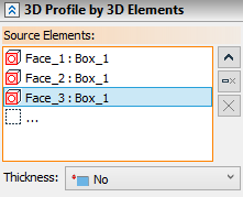
Source 3D elements are selected using ![]() in the 3D scene, model elements window or model tree. Pay attention to active filters on the Filter Toolbar, when selecting elements. Selected elements are added to the Source Elements list in the Parameters window. You can Expand
in the 3D scene, model elements window or model tree. Pay attention to active filters on the Filter Toolbar, when selecting elements. Selected elements are added to the Source Elements list in the Parameters window. You can Expand ![]() , Collapse
, Collapse ![]() , Clear
, Clear ![]() the list or Delete Element from the List
the list or Delete Element from the List ![]() using buttons located on the right side.
using buttons located on the right side.
![]() 3D Profile by an existing 3D Profile
3D Profile by an existing 3D Profile
Using an existing 3D profile as a source element results in creating a 3D profile equidistant to the source one. Source profile can be single- or multi-contoured.
Source 3D Profile can only be flat, when creating an equidistant profile.
Offset of an equidistant profile can be defined in two ways:
•By a numerical value of the offset distance between source profile and equidistant profile. Setting a zero offset value results in creating a copy of the source profile.
•By defining a point for the equidistant profile to pass through. If selected node doesn't belong to plane of source profile, it is projected onto such plane and projection is used for creating an equidistant profile.
|
1 – source profile 2 – point 3 – resulting equidistant 3D profile |
When creating an offset, three ways of handling gaps between the offset lines are possible:
•Round – rounds are constructed between the ends of the neighboring lines of the resulting contour.
•Extend – the gaps are closed by straight lines tangent to the offset lines at their ends.
•Natural – the curves that make the original contour are continued naturally. Straight lines are continued straight, arcs - round.
|
|
|
Round |
Extend |
Natural |
If the source profile contains inner loops, their handling will be defined separately, regardless of the offset distance sign. One of the two options can be chosen:
•Enlarge – offsets to inner contours are constructed by expanding the original contours.
•Decrease – offsets to inner contours are constructed by shrinking the original contours.
|
|
Enlarge |
Decrease |
To create an equidistant profile you need to select a source profile first.
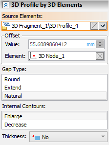
Offset is set in the Value input box, with the option to switch units of measurement. Point defining an offset can be selected using ![]() in the 3D scene, model elements window or model tree upon activating the Element input box. When point is selected, the resulting offset value is displayed in the Value input box, but it becomes non-editable. Clear
in the 3D scene, model elements window or model tree upon activating the Element input box. When point is selected, the resulting offset value is displayed in the Value input box, but it becomes non-editable. Clear ![]() the point selection using the button located in the right side of the Element input box, if you want to be able to type value again. The way of handling gaps and inner loops can be selected in Gap Type and Internal Contours lists.
the point selection using the button located in the right side of the Element input box, if you want to be able to type value again. The way of handling gaps and inner loops can be selected in Gap Type and Internal Contours lists.
![]() 3D Profile by faces of solid body or surface
3D Profile by faces of solid body or surface
When using a face (or set of faces) of solid or surface as a source element, the resulting 3D profile represents a segment of face's base surface bounded by loops (closed sequences of edges) limiting the base face. The resulting profile in this case always coincides with source elements. All faces in the selected set should belong to the same body and faces should be adjacent to each other.
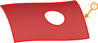
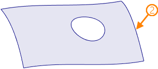
1 - source face; 2 - resulting 3D profile
Source face (or set of faces) should be selected to create a 3D profile in this mode.
The resulting 3D profile in this mode represents a segment of loop's parent face's base surface. The difference between this mode and the previous one is that here the resulting profile won't have inner contours regardless of presence of holes in the source loop's parent face.
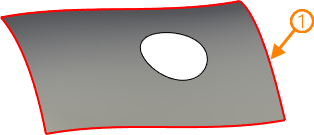
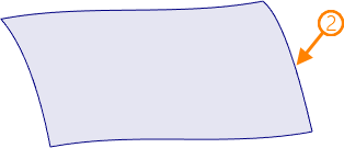
1 - source loop; 2 - resulting 3D profile
In cases where source loop is a boundary of two periodical base surfaces, it is possible to switch between base surfaces.
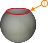
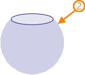
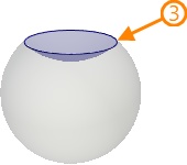
1 - source loop; 2, 3 - resulting 3D profiles depending on the selected base surface
Source loop should be selected to create a 3D profile in this mode.
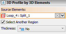
Switching between base surfaces limited by the same loop is performed using the Select Another Region checkbox.
![]() 3D profile by closed sequence of edges
3D profile by closed sequence of edges
This mode of 3D profile creation uses closed sequence of edges belonging to various elements of the model. You can also select a sequence of edges belonging to the same object, but the result in such case will be identical to 3D profile by loops. Geometry of a profile is fully defined by selected edges and their parents.
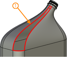
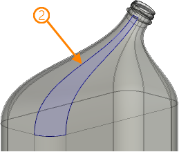
1 - source sequence of edges; 2 - resulting 3D profile
This mode allows to create 3 profile based on a single closed 3D path. The path itself can be based on edges of several object (faces of solids and surfaces, 3D profiles) and other 3D paths.
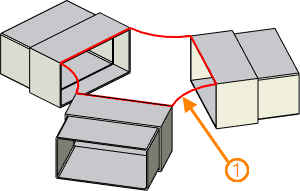
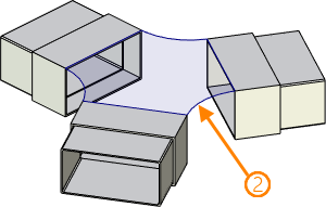
1 - source 3D path (closed); 2 - resulting 3D profile