3D Profile Projection |
  
|
The command can be called in one of the following ways:
Icon |
Ribbon |
|
3D Model > Construct > 3D Profile Projection Sheet Metal (3D) > Construct > 3D Profile Projection Surfaces > Construct > 3D Profile Projection Weld > Construct > 3D Profile Projection Primitives > Construct > 3D Profile Projection Support Geometry > 3D Profile > 3D Profile Projection |
Keyboard |
Textual Menu |
<3KRJ> |
Construct > 3D Profile > 3D Profile Projection |
Automenu of the |
|
<J> |
3D profile Projection to Face |
This command allows creating a new profile by transferring the original flat profile to a face or set of faces in the body.
Upon calling the command you need to select one of the two available modes:
•![]() Project 3D Profile to Face (or set of faces)
Project 3D Profile to Face (or set of faces)
•![]() Wrap 3D Profile on Set of Faces
Wrap 3D Profile on Set of Faces
The set of available parameters depends on the selected mode.
|
1 – source 3D profile |
In this mode a source 3D profile is projected onto a face or a set of adjoining faces of a solid or surface body. Upon selecting a face, it is not required for the final projection to fully fit such face (though in some cases abrupt projections can not be generated), but it is required to avoid breaks in projection. Upon selecting a body, it is required for the final projection to fully fit faces of such body and it is also required to avoid breaks in projection. The projecting direction is defined either by a single object capable for defining a direction (straight 3D path, edge, LCS, workplane etc.) or by two geometrical points (3D nodes, vertices etc.).
|
1 – source 3D profile 2 – source face or body 3 – points defining the projecting direction 4 – projected 3D profile |
If elements defining the projecting direction are not selected, the direction can be either normal to the selected face (or nearest face of the selected body) or normal to the source 3D profile.
|
1 – source 3D profile |
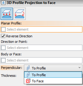
This mode can be activated using the ![]() Project 3D Profile to Face button in the Parameters window. Then you need to subsequently select a source 3D profile (displayed in the Planar Profile input box), and a face or a body defining the set of faces for projecting (displayed in the Body or Face input box). Objects can be selected using
Project 3D Profile to Face button in the Parameters window. Then you need to subsequently select a source 3D profile (displayed in the Planar Profile input box), and a face or a body defining the set of faces for projecting (displayed in the Body or Face input box). Objects can be selected using ![]() in the 3D scene, model elements window or model tree.
in the 3D scene, model elements window or model tree.
Object defining a projecting direction can be selected upon activating the Direction or Point input box. Upon selecting a point the additional Second Point input box appears.
You can Clear ![]() the selection of any object using the button located in the right side of the corresponding input box.
the selection of any object using the button located in the right side of the corresponding input box.
By default, the system automatically enables the Reverse Direction checkbox if selected projecting direction is opposite to direction from source profile to face. However you can enable or disable it manually if necessary. If elements defining the projecting direction are not selected, you can select direction either ![]() To Profile or
To Profile or ![]() To Face in the Perpendicular drop-down list.
To Face in the Perpendicular drop-down list.
This mode allows creating a new profile by wrapping the original profile on a face or set of faces in the body. A point is selected in the profile plane to be coincided to a point in the face. After coinciding points by changing the profile's position, the profile is wrapped around the face, as if a paper label on the bottle. 3D nodes are used as points on profile, any objects capable of defining a point are used as points on face. The initial 3D profile should be flat.
The profile transformation is performed without rips or shrinkages of its surface – areas of the original and the resulting profiles are equal. This condition poses restrictions on the used faces or sets of faces.
The faces allowed for wrapping profile are those that can be created by simple extruding. However, those don't have to be produced by the extrusion operation per se. For example, a cylinder is allowed, since it can be created by simple extruding, even if it was actually created by the rotation. On the other hand, a cone, sphere or torus is not allowed, since it cannot be created by the simple extrusion.
A plane orthogonal to all used faces is constructed through the selected 3D node on the face. If the selected faces were constructed by an extrusion, then this plane would have been orthogonal to the extrusion direction. The profile will be wrapped along the intersection line between this plane and the selected faces. At this point, two possibilities exist for defining the direction of the profile wrapping along the intersection line. The profile can be laid on either side of the reference point (see the diagram).
|
1 – source 3D profile 2 – first point on profile 3 – first point on face 4 – virtual plane orthogonal to selected faces 5 – virtual intersection line between faces and plane 6 – two possible directions of wrapping |
The plane orthogonal to the selected faces, the intersection line between the plane and the faces and the direction vector of wrapping the profile are not displayed in the scene. Those are shown in the diagrams for illustration purpose only.
To fully define the direction of wrapping the profile, it is necessary to select the second point on the used faces. The selected node will define which out of the two possibilities should be used as the direction of wrapping the profile.
|
|
1 – second point on face defining the direction of wrapping 2 – direction of wrapping 3 – resulting profile |
|
If the set of faces is defined in such a way, that the first point belongs to a side face, then the wrapping direction is determined automatically – towards the adjoining faces. This is the case when you do not have to select the second point on the face.
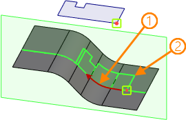
1 - automatically detected direction of wrapping
2 - resulting profile
The vector that defines the profile orientation on the face (set of faces) can be defined in two ways: by using the second point on the profile plane, or without it. This vector is not displayed in the scene, and is shown in the diagrams for clarity.
When using the second point, the start and the end of the new vector will be defined by the first and second points on the profile plane.
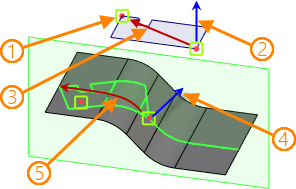
1 - second point on profile
2 - direction normal to source profile
3 - profile-orienting vector
4 - direction normal to face
5 - wrapping direction
In the cases, when the second point on the profile plane is not selected, the direction is determined by the following algorithm:
•The wrapping direction vector beginning at the first point on the surface is projected onto the profile plane. This gives the direction of the new vector for profile orientation.
•The start of the profile-orienting vector is placed in the first point on the profile plane.
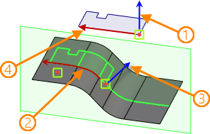
1 - direction normal to source profile
2 - wrapping direction
3 - direction normal to face
4 - profile-orienting vector
The arrows that are drawn from the first point on the profile and on the face show the normal directions to the profile plane and to the surface. When wrapping the profile, the profile plane is reoriented to have its normal coincide with the normal to the surface in the first selected point. The normal direction of the profile plane can be flipped to the opposite. This allows turning the wrapped profile 180° about the wrapping direction axis.
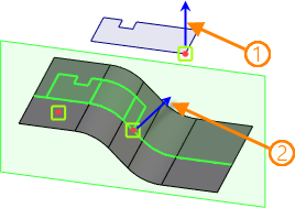
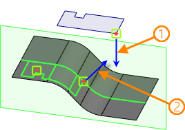
1 - direction normal to source profile plane
2 - direction normal to face
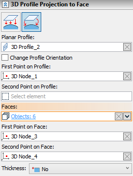
This mode is activated using the ![]() Wrap 3D Profile on Set of Faces button in the Parameters window. Then you have to subsequently select Planar Profile, First Point on Profile, Faces for the profile to be wrapped on, First Point on Face and Second Point on Face.
Wrap 3D Profile on Set of Faces button in the Parameters window. Then you have to subsequently select Planar Profile, First Point on Profile, Faces for the profile to be wrapped on, First Point on Face and Second Point on Face.
Additionally you can select Second Point on Profile if necessary.
Objects can be selected using ![]() in the 3D scene, model elements window or model tree. Selected objects are displayed in corresponding input boxes of the Parameters window.
in the 3D scene, model elements window or model tree. Selected objects are displayed in corresponding input boxes of the Parameters window.
You can Clear ![]() the selection of any object using the button located in the right side of the corresponding input box.
the selection of any object using the button located in the right side of the corresponding input box.
