3D Profile by Surface Unfolding |
  
|
The command can be called in one of the following ways:
Icon |
Ribbon |
|
3D Model > Construct > 3D Profile by Unfolding Sheet Metal (3D) > Construct > 3D Profile by Unfolding Surfaces > Construct > 3D Profile by Unfolding Weld > Construct > 3D Profile by Unfolding Primitives > Construct > 3D Profile by Unfolding Support Geometry > 3D Profile > 3D Profile by Unfolding |
Keyboard |
Textual Menu |
<3KRS> |
Construct > 3D Profile > 3D Profile by Unfolding |
Automenu of the |
|
<S> |
Unfold Surfaces |
This command allows to create a flat 3D profile by unfolding a face or set of faces using either analytical or iterative method of unfolding. The resulting profile lays in a plane tangent to the initial face. Profile passes through the tangency point. Tangency point should be selected on the initial face.
Upon calling the command it is necessary to select an initial face (or set of faces). Faces can be selected using ![]() in the 3D scene or in the model tree, when the following automenu option is active:
in the 3D scene or in the model tree, when the following automenu option is active:
|
<O> |
Select Surfaces |
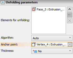
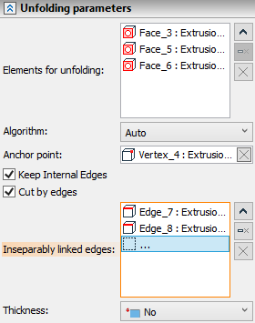
Selected faces are displayed in the Elements for unfolding list in the Parameters window. You can Expand ![]() , Collapse
, Collapse ![]() , Clear
, Clear ![]() the list or Delete Element from the List
the list or Delete Element from the List ![]() using buttons located on the right side.
using buttons located on the right side.
The next step of constructing a 3D profile is the selection of unfolding method. Following options are available in the Algorithm drop-down list:
•Auto
First, the system tries to apply the analytical method of unfolding. If it turns out to be impossible, the iterative method is applied.
•Iterative
Iterative method includes approximation of initial surface's mesh.
The set of available parameters depends on the selected algorithm.
Tangency point of initial face and resulting profile can be selected using ![]() in the 3D scene or in the model tree, when the following automenu option is active:
in the 3D scene or in the model tree, when the following automenu option is active:
|
<A> |
Select 3D node as tangency point of profile and source face |
The selected point is displayed in the Anchor point input box in the Parameters window and can be Cleared ![]() using the button in the right side of the input box.
using the button in the right side of the input box.
Automatic selection of unfolding algorithm
The analytical method of an unfolding construction is used for developable surfaces. Developable surfaces are the ruled surfaces that can be unfolded so that all their points are combined with the plane without any damage to the surface (gaps or folds). Such surfaces can be either closed (periodic) or unclosed.
|
1 – initial face |
The point of tangency of profile and face can be set by any 3D object that can define the point (for example, a 3D node or a vertex of the body). The specified point must lie on the initial face.
If the selected face is closed (periodic), the point of tangency of the profile and the face is used to specify the split line of the unfolding. The splitting is performed along a straight generatrix line passing through this point.
|
1 – initial face |
When unfolding a closed cylindrical or conical surface, it is possible to select other objects defining the split line.
In case of building a 3D profile as an unfolding of a closed cylindrical surface, the unfolding split line can pass:
•Along a generatrix passing through a tangency (anchor) point;
•Along a generatrix passing through an additional 3D point;
•Along a 3D path, which must lie on the same geometric surface as the initial face (for example, you can create an arbitrary 3D path and project it onto the face or build a path in a cylindrical coordinate system with the same position and radius as the unfolding face) and its ends must lie on the outer edges of the face.
An additional object defining the split line can be selected in the 3D scene or in the model tree upon selecting an initial closed cylindrical face an activating the following automenu option:
|
<S> |
Select Split Line |
Selected object is displayed in the Splitting element input box in the Parameters window and can be Cleared ![]() using the button in the right side of the input box.
using the button in the right side of the input box.
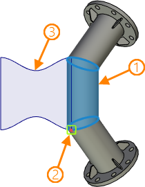
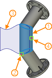
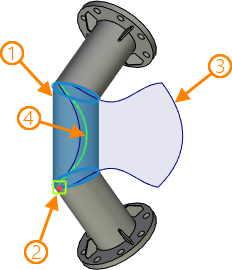
1 - initial closed cylindrical face
2 - tangency (anchor) point
3 - resulting 3D profile (unfolding of the initial face)
4 - additional object defining the split line
In the case of building a 3D profile as an unfolding of a closed conical surface, the unfolding split line can pass:
•Along a generatrix passing through a tangency (anchor) point;
•Along a generatrix passing through an additional 3D point.
An additional point defining the split line can be selected in the 3D scene or in the model tree upon selecting an initial closed conical face an activating the following automenu option:
|
<S> |
Select 3D node to define split line |
Selected object is displayed in the Splitting element input box in the Parameters window and can be Cleared ![]() using the button in the right side of the input box.
using the button in the right side of the input box.
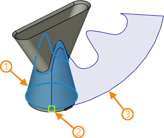
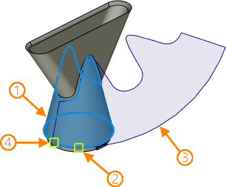
1 - initial closed conical face
2 - tangency (anchor) point
3 - resulting 3D profile (unfolding of the initial face)
4 - additional point defining the split line
Unfolding Set of Faces using the Automatic Algorithm
When unfolding a set of faces, such faces should have common edges.
If there is at least one non-developable surface in the set of faces, then the system uses an iterative algorithm for constructing an unfolding, which gives an approximate result.
When creating a profile, several solutions may occur. By default, the system automatically chooses an optimal solution. In order to obtain a specific variant of the profile construction, you can additionally select “inseparable” edges, which are used as unfolding lines. When specifying edges, you should set connections between all faces in the set. Otherwise, the face, which isn't connected by an “inseparable” edge to any other face in the set, will be ignored during profile creation.
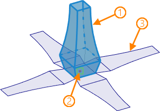
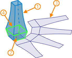
1 - initial set of faces
2 - tangency (anchor) point
3 - resulting 3D profile (unfolding of the initial set of faces)
4 - set of inseparable edges
If you want to select inseparable edges, you need to enable the Cut by edges checkbox first. Then edges can be selected using ![]() in the 3D scene upon activation of the following automenu option:
in the 3D scene upon activation of the following automenu option:
|
<E> |
Select inseparably linked edges |
Selected Inseparably linked edges are displayed in the eponymous list in the Parameters window. You can Expand ![]() , Collapse
, Collapse ![]() , Clear
, Clear ![]() the list or Delete Element from the List
the list or Delete Element from the List ![]() using buttons located on the right side.
using buttons located on the right side.
By default, edges separating faces of the set are deleted on the resulting 3D profile. Enable the Keep Internal Edges checkbox if you want to keep them.
|
|
Internal edges are kept |
Internal edges are deleted |
Iterative Algorithm of Unfolding
The iterative method is used for non-developable surfaces. Non-developable surfaces include non-linear surfaces and those ruled surfaces that cannot be turned into a plane without damaging the surface. First, the system replaces the original surface by segments of developable surface in such way that the result is approximately resembles the original surface. Then each of those segments is unfolded and unfoldings of segments form a resulting 3D profile. For applying this method the surface must be unclosed. The resulting profile may significantly differ from the original surface due to approximation.
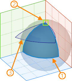
1 - initial face
2 - tangency (anchor) point
3 - resulting 3D profile (unfolding of the initial face)
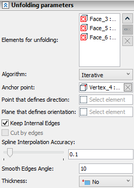
When using the iterative algorithm, vertices of the initial face are only allowed as the tangency (anchor) point.
To define the orientation of the resulting profile in the plane of tangency, it is possible to specify an additional 3D point defining the direction of projection. The resulting vector (5) formed by the anchor (tangency) point (1) and the projection of the additional point (3) will coincide with the vector (4) formed by the anchor (tangency) point and the additional point itself (2).
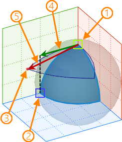
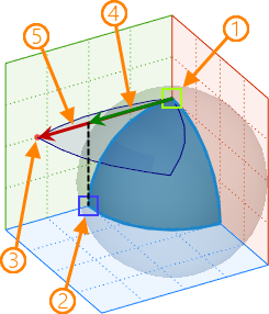
The additional point can be selected in the 3D scene or in the model tree using the following automenu option:
|
<D> |
Select Point to Define Profile Orientation |
Selected point is displayed in the Point that defines direction input box in the Parameters window and can be Cleared ![]() using the button in the right side of the input box.
using the button in the right side of the input box.
You can also set a plane in parallel to which the resulting profile will be located.
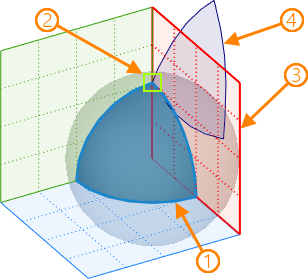
The plane can be selected in the 3D scene or in the model tree using the following automenu option:
|
<P> |
Select Plane to Define Unfolding Direction |
Selected point is displayed in the Plane that defines orientation input box in the Parameters window and can be Cleared ![]() using the button in the right side of the input box.
using the button in the right side of the input box.
The accuracy of the resulting profile's contour can be adjusted using following parameters:
•Spline Interpolation Accuracy - the coefficient in range from 0.000001 to 1.
•Smooth Edges Angle - the max allowed angle (in degrees) between edges to consider them smoothly connected; it is used upon automatic smoothing of the initial result.

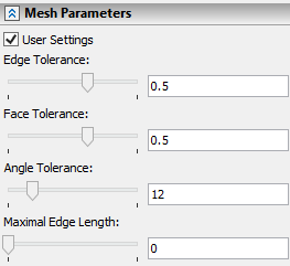
The accuracy of initial face approximation can be adjusted using following Mesh Parameters:
•Edge Tolerance - max distance between edges of the initial face and edges of approximated faces.
•Face Tolerance - max distance between the initial face and approximated faces.
•Angle Tolerance - max angle (in degrees) between edges of the initial face and edges of approximated faces. The angle is measured a sum of angles between edges of approximated faces and lines tangent to the initial edge at its ending and starting points. Also the same parameter defines the max angle between between the initial face and approximated faces.
•Maximal Edge Length - max length of the approximated edge. If value is set to zero, this parameter is ignored upon approximation.
Unfolding Set of Faces using the Iterative Algorithm
Iterative algorithm can also be used for unfolding set of faces. However, the set should not form a closed contour, because this algorithm doesn't support cutting by edges. The Keep Internal Edges checkbox is still available.
|
|
Internal edges are kept |
Internal edges are deleted |