3D Node by Faces and Offsets |
  
|
The command can be called in one of the following ways:
Icon |
Ribbon |
|
Support Geometry > 3D Node > 3D Node by Faces and Offsets |
Keyboard |
Textual Menu |
<3KNO> |
|
Automenu of the |
|
<O> |
By Faces and Offsets |
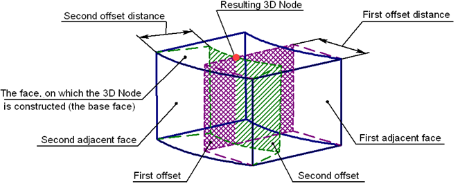
Creating a 3D node by faces and offsets from a solid is a special case of creating a node on a face. In this mode, first specify the base face for the node to be placed on. The required node position on this face is defined using two additional faces of the same body, adjacent to the base face (having a common edge), and their offsets. To create the node, offsets are constructed from the additional faces at the specified distances. The node is defined as the intersection point of the base face and the offsets.
All three faces can have the underlying surface of any type (a plane, torus, sphere, cone, spline surface). Alternatively, the additional faces can be selected by selecting the edges that join the faces with the base face.
In this mode, 3D node construction is done as follows:
•The offsets from the additional faces are constructed. The offset distances are defined by the values entered for those faces. In the case of a positive distance, the offset is constructed inside the body, negative - outside.
•An intersection of the base face and the offsets of the additional faces are calculated. The resulting intersection will be the point of the 3D node creation.
In simple cases, the face surfaces can be extended beyond the bounds (both the base and the offsets). For a plane and cone, this extension is unlimited, while for a torus or a sphere it is closed. This allows, for example, creating a node beyond the bounds of the base face, yet lying on its underlying surface (when the offset distance is negative). This also allows constructing 3D nodes in the situations when the offsets from the additional side faces do not intersect with the base face.

After activating this method, you must select the original surface on which the 3D node will lie, as well as additional faces. Instead of additional faces, you can select the edges of the source surface that define them. The selection is performed in the 3D scene (using ![]() ) or in the model tree.
) or in the model tree.
The selected objects are displayed in the corresponding fields on the By Faces and Offsets tab in the parameters window. Cancel the selected object and re-select it using the Clear ![]() button . The X and Y input fields are used to specify equidistant offsets to the side faces that determine the position of the 3D node being created. When you select the Reverse option, the offset direction of the equidistant changes: the position of the node on the base surface will correspond to negative offset values. If the flag is disabled, positive offsets are directed inside the body, i.e. the node is created on the surface.
button . The X and Y input fields are used to specify equidistant offsets to the side faces that determine the position of the 3D node being created. When you select the Reverse option, the offset direction of the equidistant changes: the position of the node on the base surface will correspond to negative offset values. If the flag is disabled, positive offsets are directed inside the body, i.e. the node is created on the surface.